

 Portable Chiller
 Air-Cooled Chiller
 Water-cooled Chiller
 Low-temperature Chiller
 Custom Industrial Chiller


Wafer processing is one of the most thermally sensitive manufacturing environments in modern industry. Unlike conventional industrial cooling, semiconductor temperature control operates at a scale where nanometer-level pattern fidelity, etch uniformity, and deposition accuracy can all be influenced by temperature fluctuations as small as ±0.05°C.
In this context, a closed loop chiller is not simply a “cooling machine.” It is a precision thermal control system integrated into the process architecture of wafer fabrication equipment. Its role is to maintain ultra-stable thermal conditions across tools such as lithography systems, etching chambers, deposition reactors, and metrology platforms.
The thermal control challenge in semiconductor manufacturing is characterized by:
- Extreme precision requirements: Temperature stability often within ±0.05–0.1°C for critical processes
- Dynamic load profiles: Rapid thermal cycling with time constants of seconds to minutes
- Multi-zone thermal management: Independent control of multiple temperature zones within a single tool
- Ultra-high purity requirements: DI water resistivity >18 MΩ·cm, particle counts <1 per mL at 0.05 μm
To understand why closed loop systems are essential, it is necessary to break down both the system architecture and the thermal physics behind wafer processing.
Why Thermal Control Is Critical in Wafer Processing
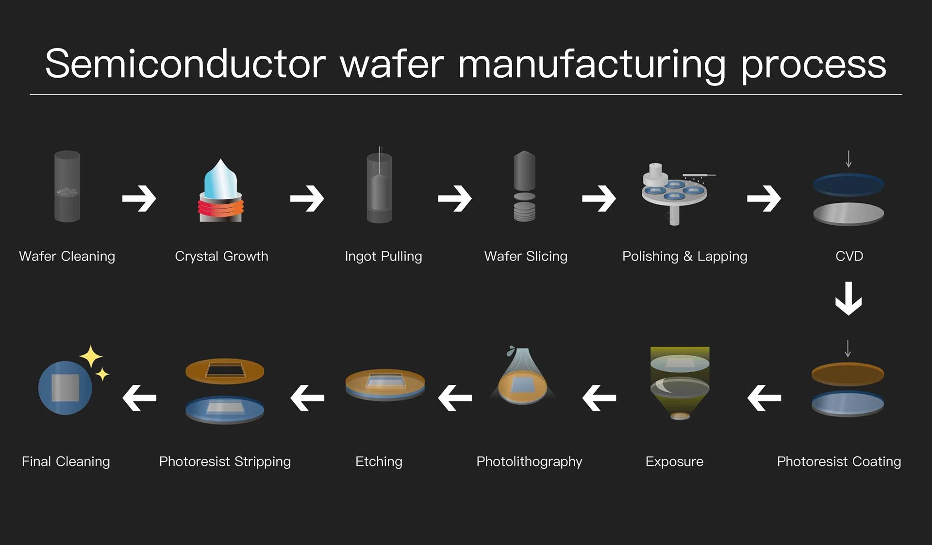
Semiconductor wafers are manufactured at nanometer-scale precision. At this level, even extremely small thermal deviations can lead to measurable process variation through multiple mechanisms:
Thermal Effects on Process Parameters
| Process | Thermal Effect Mechanism | Temperature Sensitivity | Impact of ±0.1°C Deviation |
|---|---|---|---|
| Photolithography (DUV/EUV) | Photoresist viscosity, wafer expansion | ±0.02 nm/°C (CD variation) | CD shift: 0.2–0.5 nm |
| Plasma Etching | Etch rate, selectivity, profile | ±1–3%/°C (etch rate) | Etch depth variation: 2–5 nm |
| CVD Deposition | Reaction kinetics, film stress | ±2–5%/°C (deposition rate) | Thickness non-uniformity: 0.5–1% |
| Wet Processing | Chemical reaction rate, diffusion | ±5–10%/°C (reaction rate) | Etch rate variation: 5–10% |
| Ion Implantation | Beam stability, wafer charging | ±0.5%/°C (dose uniformity) | Dose variation: 0.1–0.3% |
Temperature directly affects:
- Photoresist behavior during lithography: Viscosity changes of 2–3% per °C affect spin coating uniformity; thermal expansion of silicon (α = 2.6×10⁻⁶/°C) causes overlay errors
- Etch rate consistency: Arrhenius relationship governs chemical reaction rates; typical activation energy of 0.3–0.8 eV results in 2–5%/°C sensitivity
- Thin film deposition uniformity: Surface reaction kinetics and gas-phase chemistry both temperature-dependent
- Chemical reaction stability in wet processes: Etch selectivity and surface roughness affected by temperature
- Dimensional accuracy at micro and nano scale: Thermal expansion of wafer and chuck affects registration
Temperature Stability Requirements by Process Node
| Technology Node | Feature Size | Temperature Stability | Thermal Budget | Typical Applications |
| 28 nm and above | ≥28 nm | ±0.2–0.5°C | Less critical | General logic, analog |
| 14–20 nm | 14–20 nm | ±0.1–0.2°C | Moderate | FinFET, advanced logic |
| 7–10 nm | 7–10 nm | ±0.05–0.1°C | Critical | Advanced FinFET |
| 5 nm and below | ≤5 nm | ±0.02–0.05°C | Extremely critical | GAA, advanced nodes |
| EUV Lithography | 7 nm and below | ±0.01–0.02°C | Ultra-critical | Scanner optics, reticle |
At this level of precision, conventional cooling systems are insufficient, and closed loop chiller systems become essential.
Vapor-Compression Refrigeration Thermodynamics
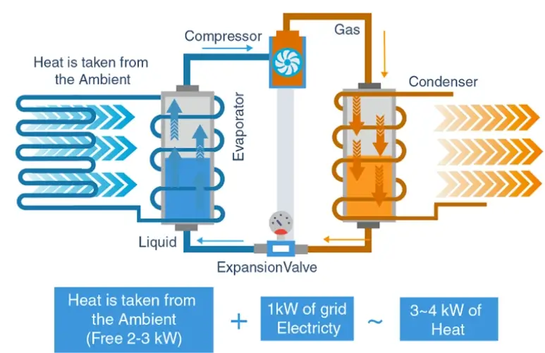
Understanding the thermodynamic basis of closed loop chillers is essential for proper system specification and optimization.
Pressure-Enthalpy (P-h) Cycle Analysis
The vapor-compression refrigeration cycle can be analyzed on a P-h diagram, showing four distinct processes:
Ideal Vapor-Compression Cycle (Standard Rating Conditions):
Process 1→2 (Isentropic Compression):
Wcomp = ṁ × (h2 – h1)
Process 2→3 (Isobaric Condensation):
Qcond = ṁ × (h2 – h3)
Process 3→4 (Isenthalpic Expansion):
h3 = h4 (throttling, no work)
Process 4→1 (Isobaric Evaporation):
Qevap = ṁ × (h1 – h4)
Coefficient of Performance:
COP = Qevap / Wcomp = (h1 – h4) / (h2 – h1)
Refrigerant Selection for Semiconductor Chillers
| Refrigerant | GWP | ODP | Tcrit | Pevap @ -10°C | Pcond @ 40°C | Application |
| R-134a | 1430 | 0 | 101.1°C | 2.0 bar | 10.2 bar | Standard precision |
| R-410A | 2088 | 0 | 71.4°C | 6.2 bar | 24.2 bar | High capacity |
| R-407C | 1774 | 0 | 86.2°C | 3.5 bar | 16.5 bar | Retrofit applications |
| R-1234ze | 1 | 0 | 109.4°C | 1.4 bar | 7.4 bar | Low-GWP, new designs |
| R-513A | 573 | 0 | 96.5°C | 1.8 bar | 9.5 bar | R-134a replacement |
For semiconductor applications, refrigerant selection considers:
- Temperature glide: Zeotropic blends (R-407C) have temperature glide during phase change, affecting control precision
- Pressure ratio: Lower pressure ratios reduce compressor work and improve efficiency
- Environmental compliance: EU F-Gas regulations and EPA SNAP program requirements
- Material compatibility: POE oils for HFC refrigerants, compatibility with seals and gaskets
Closed Loop Chiller System Architecture
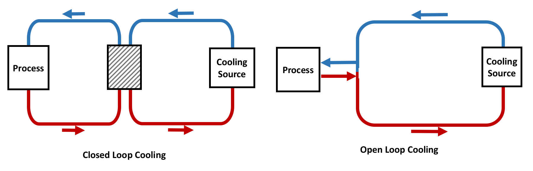
A semiconductor-grade closed loop chiller is composed of multiple interdependent subsystems. Each one plays a distinct role in achieving thermal precision.
Compressor System (Thermal Energy Driver)
The compressor is the core energy conversion component of the chiller. It converts low-pressure refrigerant vapor into high-pressure, high-temperature vapor, enabling heat rejection at the condenser stage.
| Type | Capacity Range | Modulation | Part-Load Efficiency | Temperature Stability | Best Application |
| Scroll (Fixed) | 3–50 kW | On/Off | Poor at <50% | ±0.5–1.0°C | Non-critical auxiliary |
| Scroll (Inverter) | 3–70 kW | 15–100% | Excellent | ±0.1–0.3°C | Most precision chillers |
| Screw (Fixed) | 50–500 kW | Step (25/50/75/100%) | Moderate | ±0.3–0.5°C | Large central plants |
| Screw (VFD) | 50–500 kW | 25–100% | Excellent | ±0.1–0.3°C | Large precision systems |
| Centrifugal | 200–2000 kW | Vanes + VFD | Good | ±0.2–0.4°C | Central facility cooling |
In wafer processing chillers, the key technical requirement is not just capacity, but modulation stability. Modern systems use variable frequency drives (VFDs) to maintain:
- Stable suction pressure: Typically maintained within ±0.1 bar of setpoint
- Reduced thermal overshoot: <0.3°C overshoot on load changes vs. 2–5°C for on/off control
- Smooth load adaptation: Response time <10 seconds for 50% load step change
- Minimal cycling: Reduced starts from 10–20/hour to 2–4/hour
Compressor Power vs. Frequency (Inverter Drive):
Pcomp ∝ (f/frated)³ × Prated
Where:
• f = Operating frequency (Hz)
• frated = Rated frequency (typically 50 or 60 Hz)
• Prated = Rated power at full speed
Affinity Law Application: 50% speed → ~12.5% power (theoretical)
Without this modulation, temperature oscillation would directly propagate into wafer processing instability, potentially causing:
- Critical dimension (CD) variation in lithography
- Etch depth non-uniformity across wafer
- Film thickness variation in deposition processes
Condenser System (Heat Rejection Interface)
The condenser is responsible for transferring heat from the refrigerant to the external environment. The condenser capacity must be sized to reject both the evaporator heat load and compressor work:
Condenser Heat Rejection:
Qcond = Qevap + Wcomp
For typical semiconductor chillers:
Qcond ≈ 1.2–1.4 × Qevap (depending on COP)
Air-Cooled Condensers
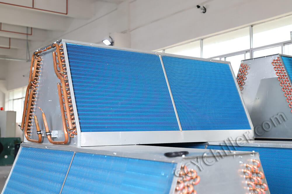
Heat is transferred to ambient air via finned coils and high-efficiency axial fans. The heat transfer coefficient for air-cooled condensers is typically 30–100 W/m²·K.
| Parameter | Typical Value | Design Consideration |
| Air-side heat transfer coefficient | 30–100 W/m²·K | Fin geometry, airflow rate |
| Face velocity | 2–4 m/s | Balances heat transfer and noise |
| Temperature approach | 8–15°C | Condensing temp – ambient temp |
| Capacity derating at high ambient | 3–5%/°C above 35°C | Critical for hot climates |
| Fan power consumption | 0.02–0.05 kW/kW cooling | Significant at part load |
In semiconductor environments, air-cooled systems are limited by:
- Ambient temperature fluctuations: Daily swings of 10–20°C can affect condensing pressure
- Lower heat transfer coefficient: Requires larger surface area and higher fan power
- Sensitivity to airflow obstruction: Dirt accumulation reduces capacity 5–15% per year
- Noise generation: Fan noise typically 65–80 dB(A) at 1 meter
Water-Cooled Condensers
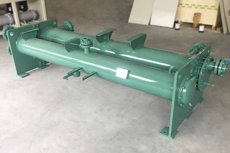
Water-cooled systems use a secondary water loop to reject heat through a cooling tower or dry cooler. The heat transfer coefficient for water-cooled condensers is typically 1000–6000 W/m²·K, approximately 25–50× higher than air.
| Parameter | Typical Value | Advantage vs. Air-Cooled |
| Water-side heat transfer coefficient | 3000–6000 W/m²·K | 50–100× higher than air |
| Overall U-value | 1000–2500 W/m²·K | Compact design possible |
| Temperature approach | 3–8°C | Lower condensing temperature |
| Condensing temperature (typical) | 32–38°C | 8–12°C lower than air-cooled |
| COP improvement | 15–25% | Lower compression ratio |
| Water consumption (cooling tower) | 1.5–2.0 L/h per kW | Requires water treatment |
Technically, water-cooled systems provide:
- Higher thermal conductivity of water: ~0.6 W/m·K vs. ~0.026 W/m·K for air
- More stable condensing temperature: Tower water typically varies ±2–3°C vs. ±10–20°C for ambient air
- Better COP: 4.5–6.5 vs. 3.0–4.5 for air-cooled at equivalent conditions
- Decoupled from ambient variability: Performance independent of outdoor conditions
In advanced fabs, water-cooled configurations dominate for precision cooling applications.
Evaporator (Primary Heat Exchange Core)
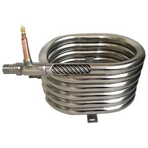
The evaporator is where heat is absorbed from the process loop. In semiconductor closed loop chillers, brazed plate heat exchangers (BPHE) are commonly used due to:
- High surface-area-to-volume ratio: 200–500 m²/m³, 3–5× higher than shell-and-tube
- Compact thermal design: Footprint 20–30% of equivalent shell-and-tube
- High heat transfer efficiency: U-values of 3000–7000 W/m²·K
- Low refrigerant charge: 30–50% less than shell-and-tube, reducing environmental impact
Evaporator Heat Transfer Analysis:
Qevap = U × A × LMTD
Where:
• U = Overall heat transfer coefficient (W/m²·K)
• A = Heat transfer area (m²)
• LMTD = Log Mean Temperature Difference (°C)
LMTD for Counter-Flow:
LMTD = (ΔT1 – ΔT2) / ln(ΔT1 / ΔT2)
| Parameter | Specification | Impact on Performance |
| Refrigerant-side coefficient | 5000–10000 W/m²·K | Primary heat transfer resistance |
| Process fluid-side coefficient | 4000–8000 W/m²·K | Depends on flow rate and viscosity |
| Overall U-value | 3000–7000 W/m²·K | Combined thermal resistance |
| Approach temperature | 1–3°C | Lower = higher efficiency but larger area |
| Pressure drop (process side) | 20–80 kPa | Affects pump sizing |
| Superheat (exit) | 5–8°C | Ensures complete evaporation |
Inside the evaporator:
- Refrigerant absorbs heat and evaporates: Phase change from liquid-vapor mixture to saturated/superheated vapor
- Process fluid (DI water or glycol mixture) is cooled indirectly: No direct contact between refrigerant and process fluid
- Thermal separation ensures contamination-free operation: Critical for semiconductor purity requirements
The evaporator is critical because even minor fouling or flow imbalance can introduce temperature drift. For a 100 kW evaporator with 5°C approach:
Fouling Impact on Heat Transfer:
1/Ufouled = 1/Uclean + Rf
Where Rf = fouling factor (m²·K/W)
Example: Rf = 0.0001 m²·K/W (typical for DI water)
Uclean = 5000 W/m²·K → Ufouled = 3333 W/m²·K
Result: 33% reduction in heat transfer capacity
Pumping System (Flow Stability Control)
The pump system defines how thermal energy is transported between the chiller and wafer equipment. Unlike standard industrial systems, semiconductor cooling requires:
- Highly stable flow control: Flow rate stability within ±1–2%
- Minimal pulsation: <2% pressure pulsation to avoid vibration transmission
- Precise flow matching to tool demand: Dynamic response to load changes within seconds
- Ultra-high purity compatibility: No contamination introduction to process fluid
Heat Transport Equation:
Q = ṁ × Cp × ΔT
Where:
• Q = Heat load (kW)
• ṁ = Mass flow rate (kg/s)
• Cp = Specific heat capacity (kJ/kg·K)
• ΔT = Temperature difference (°C)
For DI water: Cp ≈ 4.18 kJ/kg·K
Flow rate sensitivity: 10% flow variation → ~8% heat transfer variation
(at constant ΔT, assuming turbulent flow)
| Pump Type | Flow Range | Head | Pulsation | Seal Type | Application |
| Centrifugal (Magnetic Drive) | 10–500 L/min | 10–50 m | <2% | Sealless | Standard precision |
| Centrifugal (Canned Motor) | 10–300 L/min | 10–40 m | <1% | Sealless | Ultra-high purity |
| Multi-stage Centrifugal | 50–1000 L/min | 30–100 m | <3% | Mechanical/Mag | High pressure systems |
| Variable Speed (VFD) | 5–100% range | Variable | <2% | Various | Dynamic load matching |
Most advanced systems use:
- Magnetic drive pumps: Sealless design eliminates contamination risk from seal leakage; typical MTBF >50,000 hours
- Variable frequency pumps: Flow adjustment range of 5–100% with response time <5 seconds
- Redundant pump configurations: N+1 or 2N for critical applications
Flow stability is directly linked to temperature stability because:
Temperature Stability vs. Flow Stability:
ΔTstability = f(Δṁ, ΔTchiller, thermal mass)
For a typical wafer tool with 50 kW load and 5°C ΔT:
• Required flow: ṁ = Q / (Cp × ΔT) = 50 / (4.18 × 5) = 2.4 kg/s ≈ 144 L/min
• ±1% flow variation → ±0.05°C temperature variation at tool
• ±2% flow variation → ±0.1°C temperature variation at tool
Expansion Valve (Precision Refrigerant Regulation)
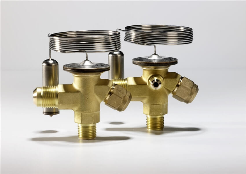
The expansion valve controls refrigerant flow into the evaporator, maintaining proper superheat and optimizing evaporator utilization.
| Type | Control Resolution | Response Time | Superheat Control | Application |
| Thermostatic (TXV) | Continuous (mechanical) | 30–60 seconds | ±2–4°C | Standard industrial |
| Electronic (EEV) | 1–5% steps | 5–15 seconds | ±0.5–1.0°C | Precision chillers |
| Electronic (Stepper) | 0.5–2% steps | 2–5 seconds | ±0.3–0.5°C | Ultra-precision |
In wafer-grade systems, electronic expansion valves (EEV) are standard. Unlike mechanical valves, EEVs allow:
- Micro-level flow adjustment: Resolution of 0.5–2% of full stroke
- Fast response to load changes: 2–15 seconds vs. 30–60 seconds for TXV
- Stable superheat control: ±0.3–1.0°C vs. ±2–4°C for TXV
- Reduced temperature oscillation: Direct impact on process temperature stability
- Adaptive control algorithms: Integration with chiller PLC for predictive control
Superheat Control Importance:
SH = Tsuction – Tsat(Psuction)
Where:
• SH = Superheat (°C)
• Tsuction = Actual suction temperature
• Tsat = Saturation temperature at suction pressure
Optimal superheat range: 5–8°C
• Too low: Risk of liquid refrigerant returning to compressor (damage)
• Too high: Reduced evaporator efficiency (10–20% capacity loss per 5°C excess SH)
Control System (Thermal Intelligence Layer)
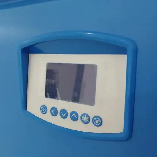
The control system is the “brain” of the closed loop chiller, coordinating all subsystems to achieve precise thermal control.
PID Control Architecture
PID Control Algorithm:
u(t) = Kp × e(t) + Ki × ∫e(t)dt + Kd × de(t)/dt
Where:
• u(t) = Control output (compressor frequency, valve position)
• e(t) = Error = Setpoint – Process variable
• Kp = Proportional gain
• Ki = Integral gain
• Kd = Derivative gain
| Parameter | Typical Range | Effect | Tuning Guidance |
| Proportional Band | 0.2–1.0°C | Response speed | Smaller = faster but risk of oscillation |
| Integral Time (Ti) | 20–120 seconds | Eliminates offset | Shorter = faster offset elimination |
| Derivative Time (Td) | 0–30 seconds | Damps oscillation | Higher = more damping |
| Sample Time | 0.1–1.0 seconds | Control frequency | Faster for precision applications |
| Output Limiting | 15–100% (compressor) | Prevents saturation | Based on compressor minimum speed |
Advanced Control Features
Modern semiconductor chillers use PLC-based or embedded microcontroller systems capable of:
- PID temperature control: Primary control loop with adaptive tuning
- Multi-sensor feedback loops: Redundant PT100 or PT1000 sensors with voting logic
- Real-time load prediction: Feedforward control based on process signals
- Compressor frequency modulation: Inverter control with 15–100% capacity range
- Flow balancing across multiple loops: Independent control of multiple process zones
- Cascade control: Primary loop (process temp) → Secondary loop (evaporator temp)
- Redundant temperature sensors: PT100/PT1000 with 4-wire configuration, accuracy ±0.1°C
- Digital twin thermal modeling: Real-time simulation for predictive control
- Fault prediction algorithms: Machine learning-based anomaly detection
- SECS/GEM interface: Semiconductor Equipment Communication Standard for fab integration
- Remote monitoring and diagnostics: IoT connectivity for predictive maintenance
The goal is not just control, but predictive stabilization of thermal behavior, anticipating load changes before they affect process temperature.
Thermal Load Characteristics in Wafer Equipment
Wafer processing equipment generates heat in highly dynamic and localized ways. Understanding these characteristics is essential for proper chiller sizing and control system design.
Dynamic Load Profiles
Unlike traditional industrial systems, semiconductor tools often have:
- Rapid thermal cycling: Load changes of 50–100% within 1–10 seconds
- Localized heat zones: Multiple independent thermal zones within one tool
- Pulsed heat loads: RF plasma, laser pulses with millisecond to second duration
- High sensitivity to return temperature: Process stability depends on inlet temperature
| Equipment | Typical Heat Load | Load Profile | Response Time Required | Temp Stability |
| Etch Chamber (RF Plasma) | 5–30 kW | Pulsed (RF on/off) | <5 seconds | ±0.1–0.2°C |
| CVD Reactor | 10–50 kW | Step changes (recipe) | <10 seconds | ±0.1–0.3°C |
| Lithography Scanner | 20–100 kW | Steady + transients | <2 seconds | ±0.01–0.05°C |
| Ion Implanter | 10–40 kW | Pulsed (beam on/off) | <5 seconds | ±0.1–0.2°C |
| Laser System | 2–15 kW | Pulsed (ms to s) | <1 second | ±0.05–0.1°C |
| Electrostatic Chuck (ESC) | 1–5 kW | Variable (process) | <10 seconds | ±0.05–0.1°C |
| Vacuum Pump | 1–10 kW | Steady state | <30 seconds | ±0.5–1.0°C |
Heat Source Analysis
Typical heat sources in wafer processing equipment include:
| Heat Source | Mechanism | Typical Power Density | Cooling Method |
|---|---|---|---|
| RF Plasma Generators | Ion bombardment, joule heating | 0.5–5 W/cm² | Direct cooling, ESC |
| Laser Systems (excimer, solid-state) | Optical absorption, waste heat | 1–10 W/cm² (localized) | Optics cooling, laser head |
| Vacuum Pumps (turbo, dry) | Friction, compression heat | 0.1–0.5 W/cm² | Jacket cooling |
| Electrostatic Chucks (ESC) | RF coupling, helium backside | 0.1–2 W/cm² | Internal channels |
| Chemical Reaction Chambers | Exothermic reactions, plasma | 0.5–3 W/cm² | Chamber walls, showerhead |
| Heater Elements | Resistive heating | 5–50 W/cm² | Process temperature control |
Because of this variability, closed loop chillers must respond quickly and maintain stable output under fluctuating loads. Key design considerations include:
- Thermal mass: Buffer tanks to dampen temperature fluctuations
- Fast-responding control: EEV and VFD compressor for rapid capacity adjustment
- Multi-zone capability: Independent temperature control for different process zones
Precision Requirements in Semiconductor Cooling
Wafer processing tools require significantly higher precision than most industrial applications. The temperature stability requirement is driven by the thermal expansion coefficient of silicon and the feature sizes being manufactured.
Thermal Expansion Impact on Overlay Error:
ΔL = α × L × ΔT
Where:
• ΔL = Length change (nm)
• α = Thermal expansion coefficient (2.6×10⁻⁶/°C for Si)
• L = Wafer diameter (mm)
• ΔT = Temperature change (°C)
Example for 300 mm wafer:
ΔT = 0.1°C → ΔL = 2.6×10⁻⁶ × 300 × 0.1 = 78 nm
For 7 nm node with 3 nm overlay budget:
Required ΔT < 0.01°C to stay within overlay tolerance
Temperature Stability Requirements by Application
| Application | Temperature Stability | Setpoint Range | Control Resolution | Sensor Accuracy |
|---|---|---|---|---|
| General industrial cooling | ±1.0°C | 5–35°C | 0.1°C | ±0.5°C |
| Advanced manufacturing tools | ±0.5°C | 10–30°C | 0.05°C | ±0.2°C |
| Semiconductor wafer processing | ±0.1–0.2°C | 15–25°C | 0.01°C | ±0.05°C |
| Critical lithography systems | ±0.01–0.05°C | 20–23°C | 0.001°C | ±0.01°C |
| EUV scanner optics | ±0.005–0.01°C | 22–24°C | 0.0005°C | ±0.005°C |
System Design Requirements for Precision Cooling
Achieving sub-0.1°C temperature stability requires:
- High-resolution temperature sensors: PT100 or PT1000 with 4-wire configuration, resolution 0.001–0.01°C
- PID or advanced predictive control: Adaptive tuning, feedforward compensation
- Variable frequency compressor control: 15–100% capacity modulation with <1% speed resolution
- Precise flow regulation: VFD pumps with <1% flow stability
- Low thermal inertia system design: Minimized fluid volume for fast response
- Thermal buffer tanks: De-couples chiller dynamics from process transients
- Multi-stage cooling architecture: Primary + secondary precision loop for critical applications
Why Closed Loop Chillers Outperform Open Systems
Thermal Stability Advantage
Closed loop systems have significantly lower thermal fluctuation because:
- No direct environmental exposure: Process fluid isolated from ambient conditions
- Controlled internal fluid volume: Known thermal mass for predictable response
- Stable heat exchange interface: Consistent heat transfer coefficients
- Precise water quality control: DI water resistivity >18 MΩ·cm maintained
| Parameter | Closed Loop | Open Loop | Improvement |
| Temperature stability | ±0.05–0.2°C | ±0.5–2.0°C | 5–10× better |
| Response time | 5–30 seconds | 30–120 seconds | 2–4× faster |
| Water quality control | DI water, >18 MΩ·cm | Tower water, variable | Ultra-pure |
| Contamination risk | Very low | High (airborne, biological) | Significant |
| Seasonal variation | Minimal | Significant | Decoupled from ambient |
Energy Efficiency at Stable Load
In semiconductor fabs, loads are relatively stable compared to industrial environments, allowing optimization for steady-state efficiency.
Energy Efficiency Metrics:
COP (Coefficient of Performance):
COP = Qcooling / Pinput
IPLV (Integrated Part Load Value):
IPLV = 0.01A + 0.42B + 0.45C + 0.12D
Where A, B, C, D = COP at 100%, 75%, 50%, 25% load
Typical Semiconductor Chiller:
• COP: 4.0–6.0 (water-cooled), 3.0–4.5 (air-cooled)
• IPLV: 5.0–7.0 (water-cooled), 3.5–5.0 (air-cooled)
Closed loop chillers optimize:
- Compressor cycling efficiency: VFD reduces cycling losses by 20–40%
- Part-load performance: IPLV typically 20–30% better than full-load COP
- Heat recovery potential: 60–80% of compressor work recoverable for facility heating
Reduced Maintenance Complexity
Because the system is sealed:
- No cooling tower maintenance: Eliminates basin cleaning, drift elimination, fill replacement
- No water contamination control: No biological growth, algae, or Legionella risk
- Reduced corrosion risk: Closed system with controlled water chemistry
- Longer system lifespan: Typical 15–20 years vs. 10–15 years for open systems
- Lower water treatment costs: Minimal chemical consumption
This is especially important in 24/7 semiconductor fabs where maintenance windows are limited.
Integration with Wafer Processing Equipment
Closed loop chillers are commonly integrated with:
| Equipment Type | Cooling Requirements | Typical Configuration | Interface Standard |
|---|---|---|---|
| Lithography Systems (DUV/EUV) | Optics, reticle, wafer stage, illumination | Multi-zone, ultra-precision | SECS/GEM, OPC-UA |
| Etching Tools (RIE, ICP, DRIE) | ESC, chamber walls, RF generator | Multi-loop, fast response | SECS/GEM |
| Deposition (CVD, PVD, ALD) | Chamber, showerhead, heater | Multi-zone, high capacity | SECS/GEM |
| Ion Implantation | Beam line, target, analyzer | Multi-loop, precision | SECS/GEM |
| Metrology (CD-SEM, AFM) | Stage, optics, electronics | Single/multi-zone | Varies |
| Vacuum Processing | Pumps, chambers, gauges | Single loop, moderate precision | Varies |
Each system may require independent thermal control zones depending on process sensitivity. Advanced fabs often deploy multi-loop chiller architectures to support different temperature zones within the same production line.
Multi-Zone Thermal Architecture
| Zone | Heat Load | Temperature | Stability | Fluid |
| Electrostatic Chuck (ESC) | 2–5 kW | -20 to +80°C | ±0.1°C | DI water/glycol |
| Chamber Walls | 3–8 kW | 20–40°C | ±0.5°C | DI water |
| RF Generator | 1–3 kW | 20–30°C | ±1.0°C | DI water |
| Vacuum Pump | 1–2 kW | 20–40°C | ±2.0°C | DI water |
| Total | 7–18 kW | — | — | — |
Redundancy in Semiconductor Cooling Systems
In semiconductor manufacturing, downtime is extremely costly. A single thermal interruption may result in:
- Wafer batch loss: $50,000–$500,000+ per lot depending on product
- Process instability: Hours to days of re-qualification
- Tool recalibration requirements: 4–24 hours of lost production
- Production delays: Ripple effects through fab schedule
Redundancy Architecture Options
| Configuration | Description | Availability | Cost Premium | Application |
| N+1 | One backup unit for N operating units | 99.5–99.9% | +15–25% | Standard production |
| 2N | Fully redundant (100% backup) | 99.9–99.99% | +80–100% | Critical tools |
| 2N+1 | Fully redundant with spare | 99.99%+ | +100–120% | Ultra-critical (EUV) |
| Dual Loop | Two independent cooling loops per tool | 99.9%+ | +50–70% | Multi-zone tools |
Closed loop chiller systems are often designed with:
- N+1 redundancy: One standby chiller for every N operating chillers
- Dual pump systems: Automatic switchover on pump failure
- Backup compressor modules: Quick-change compressor cartridges
- Parallel cooling loops: Independent loops for critical zones
- UPS for control systems: Uninterruptible power for controls and sensors
Automatic Switchover Systems
Modern redundant systems include automatic switchover capability:
- Temperature deviation trigger: Switchover when temperature exceeds ±0.2°C from setpoint
- Flow deviation trigger: Switchover when flow drops below 90% of setpoint
- Equipment fault trigger: Switchover on compressor, pump, or sensor fault
- Switchover time: <30 seconds to maintain process continuity
Conclusion
Closed loop chillers play a foundational role in modern wafer processing equipment by providing ultra-stable, contamination-free, and highly precise temperature control.
Key technical advantages of closed loop systems for semiconductor manufacturing:
- Thermal stability: ±0.05–0.2°C achievable, 5–10× better than open systems
- Contamination control: DI water quality >18 MΩ·cm maintained throughout system
- Process repeatability: Consistent thermal conditions enable high yield manufacturing
- Energy efficiency: COP of 4.0–6.0 with VFD compressors and optimized control
- Reliability: 15–20 year system lifetime with proper maintenance
Critical design considerations for semiconductor chillers:
- Compressor selection: Inverter-driven scroll or screw for modulation stability
- Evaporator design: Brazed plate for high efficiency and low refrigerant charge
- Control system: PID with adaptive tuning, feedforward, and predictive capabilities
- Redundancy: N+1 or 2N configuration for critical applications
- Integration: SECS/GEM interface for fab automation
As semiconductor technology continues to advance toward smaller nodes (<5 nm) and new architectures (GAA, chiplets), closed loop cooling systems will become even more critical in supporting next-generation wafer fabrication. The thermal precision requirements will tighten to ±0.01°C or better for critical processes, demanding continued innovation in:
- Ultra-precision temperature control algorithms
- Low-thermal-inertia system designs
- Multi-zone independent thermal management
- AI-based predictive thermal control
- Sustainable refrigerant and energy technologies
Ultimately, thermal precision directly determines yield, device performance, and manufacturing success in advanced semiconductor fabrication.
