
Xử lý wafer là một trong những môi trường sản xuất nhạy cảm với nhiệt nhất trong ngành công nghiệp hiện đại. Không giống như làm mát công nghiệp thông thường, điều khiển nhiệt độ bán dẫn hoạt động ở quy mô độ trung thực của mẫu ở cấp độ nanomet, khắc tính đồng nhất, Và độ chính xác lắng đọng đều có thể bị ảnh hưởng bởi sự dao động nhiệt độ nhỏ như ±0,05°C.
Trong bối cảnh này, máy làm lạnh vòng kín không chỉ đơn giản là một “máy làm mát”. Nó là một hệ thống điều khiển nhiệt chính xác được tích hợp vào kiến trúc quy trình của thiết bị chế tạo tấm bán dẫn. Vai trò của nó là duy trì các điều kiện nhiệt cực kỳ ổn định trên các công cụ như hệ thống in thạch bản, buồng khắc, lò phản ứng lắng đọng và nền tảng đo lường.
Thách thức về kiểm soát nhiệt trong sản xuất chất bán dẫn được đặc trưng bởi:
- Yêu cầu độ chính xác cực cao: Độ ổn định nhiệt độ thường nằm trong khoảng ±0,05–0,1°C đối với các quy trình quan trọng
- Hồ sơ tải động: Chu kỳ nhiệt nhanh với hằng số thời gian từ giây đến phút
- Quản lý nhiệt đa vùng: Kiểm soát độc lập nhiều vùng nhiệt độ trong một công cụ duy nhất
- Yêu cầu độ tinh khiết cực cao: Điện trở suất của nước DI >18 MΩ·cm, số lượng hạt <1 trên mL ở mức 0,05 μm
Để hiểu tại sao hệ thống vòng kín lại cần thiết, cần phải phân tích cả kiến trúc hệ thống và tính chất vật lý nhiệt đằng sau quá trình xử lý tấm bán dẫn.
Tại sao kiểm soát nhiệt lại quan trọng trong xử lý wafer
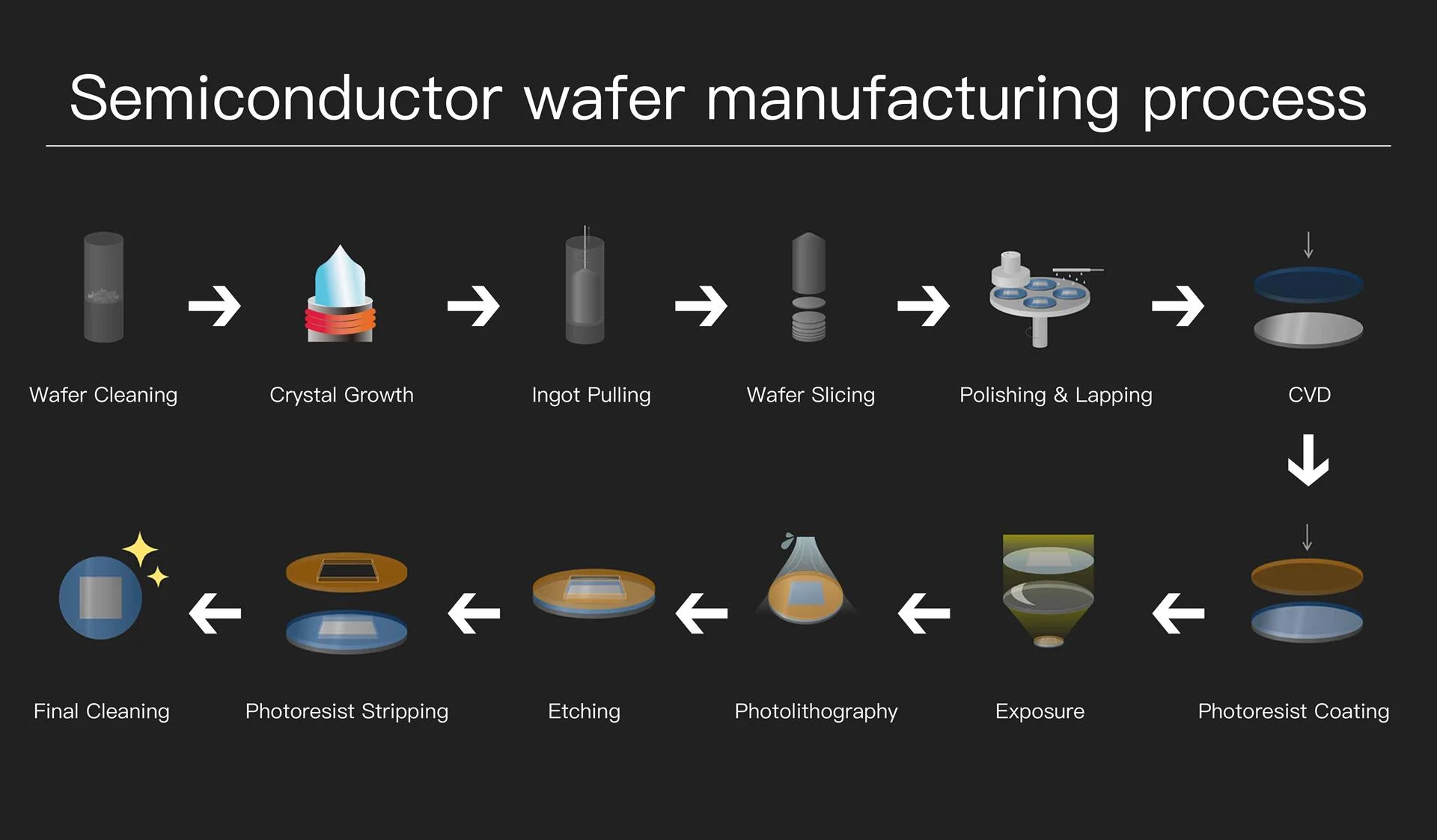
Tấm bán dẫn được sản xuất ở độ chính xác ở quy mô nanomet. Ở mức độ này, ngay cả những sai lệch nhiệt cực nhỏ cũng có thể dẫn đến sự biến đổi có thể đo lường được của quy trình thông qua nhiều cơ chế:
Hiệu ứng nhiệt trên các thông số quy trình
| Quá trình | Cơ chế hiệu ứng nhiệt | Độ nhạy nhiệt độ | Tác động của độ lệch ± 0,1°C |
|---|---|---|---|
| Quang khắc (DUV/EUV) | Độ nhớt của chất quang điện, sự giãn nở của wafer | ±0,02 nm/°C (biến thể CD) | Dịch chuyển CD: 0,2–0,5 nm |
| khắc plasma | Tốc độ ăn mòn, độ chọn lọc, hồ sơ | ±1–3%/°C (tốc độ ăn mòn) | Sự thay đổi độ sâu khắc: 2–5 nm |
| Lắng đọng CVD | Động học phản ứng, ứng suất màng | ±2–5%/°C (tốc độ lắng đọng) | Độ dày không đồng đều: 0,5–1% |
| Chế biến ướt | Tốc độ phản ứng hóa học, khuếch tán | ±5–10%/°C (tốc độ phản ứng) | Biến đổi tỷ lệ ăn mòn: 5–10% |
| Cấy ion | Độ ổn định của chùm tia, sạc wafer | ±0,5%/°C (độ đồng đều về liều lượng) | Sự thay đổi liều lượng: 0,1–0,3% |
Nhiệt độ ảnh hưởng trực tiếp đến:
- Hành vi quang điện trong quá trình in thạch bản: Sự thay đổi độ nhớt ở mức 2–3% trên mỗi °C ảnh hưởng đến tính đồng nhất của lớp phủ kéo sợi; sự giãn nở nhiệt của silicon (α = 2,6×10⁻⁶/°C) gây ra lỗi lớp phủ
- Tính nhất quán của tốc độ khắc: Mối quan hệ Arrhenius chi phối tốc độ phản ứng hóa học; năng lượng kích hoạt điển hình là 0,3–0,8 eV mang lại độ nhạy 2–5%/°C
- Tính đồng nhất lắng đọng màng mỏng: Động học phản ứng bề mặt và hóa học pha khí đều phụ thuộc vào nhiệt độ
- Độ ổn định phản ứng hóa học trong quy trình ướt: Độ chọn lọc ăn mòn và độ nhám bề mặt bị ảnh hưởng bởi nhiệt độ
- Độ chính xác kích thước ở quy mô micro và nano: Sự giãn nở nhiệt của wafer và mâm cặp ảnh hưởng đến việc đăng ký
Yêu cầu về độ ổn định nhiệt độ theo nút quy trình
| Nút công nghệ | Kích thước tính năng | Ổn định nhiệt độ | Ngân sách nhiệt | Ứng dụng điển hình |
| 28nm trở lên | ≥28nm | ±0,2–0,5°C | Ít quan trọng hơn | Logic chung, tương tự |
| 14–20nm | 14–20nm | ±0,1–0,2°C | Vừa phải | FinFET, logic nâng cao |
| 7–10nm | 7–10nm | ±0,05–0,1°C | Phê bình | FinFET nâng cao |
| 5nm trở xuống | 5nm | ±0,02–0,05°C | Cực kỳ quan trọng | GAA, nút nâng cao |
| Kỹ thuật in thạch bản EUV | 7nm trở xuống | ±0,01–0,02°C | Cực kỳ quan trọng | Máy quét quang học, mặt kẻ ô |
Ở mức độ chính xác này, hệ thống làm mát thông thường là không đủ và hệ thống làm lạnh vòng kín trở nên cần thiết.
Nhiệt động lực học làm lạnh nén hơi
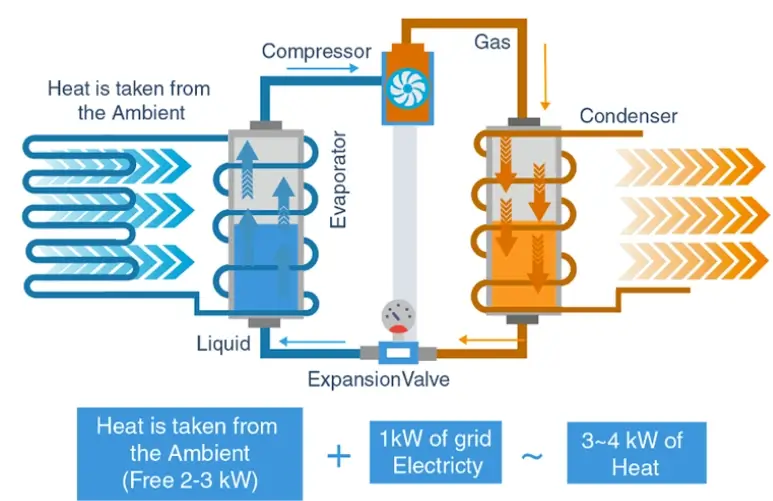
Hiểu cơ sở nhiệt động lực học của thiết bị làm lạnh vòng kín là điều cần thiết để có thông số kỹ thuật và tối ưu hóa hệ thống phù hợp.
Phân tích chu trình áp suất-Entanpy (P-h)
Chu trình làm lạnh nén hơi có thể được phân tích trên sơ đồ P-h, hiển thị bốn quy trình riêng biệt:
Chu trình nén hơi lý tưởng (Điều kiện đánh giá tiêu chuẩn):
Quá trình 1→2 (Nén đẳng entropy):
Wmáy tính = ṁ × (h2 – h1)
Quy trình 2→3 (Ngưng tụ đẳng áp):
Q.điều kiện = ṁ × (h2 – h3)
Quy trình 3→4 (Mở rộng Isenthalpic):
h3 = h4 (thắt ga, không có việc gì)
Quy trình 4→1 (bay hơi đẳng áp):
Q.trốn tránh = ṁ × (h1 – h4)
Hệ số hiệu suất:
COP = Qtrốn tránh / Wmáy tính = (h1 – h4) / (giờ2 – h1)
Lựa chọn chất làm lạnh cho thiết bị làm lạnh bán dẫn
| Môi chất lạnh | GWP | ODP | Tchí mạng | Ptrốn tránh @ -10°C | Pđiều kiện @ 40°C | Ứng dụng |
| R-134a | 1430 | 0 | 101,1°C | thanh 2.0 | 10,2 thanh | Độ chính xác tiêu chuẩn |
| R-410A | 2088 | 0 | 71,4°C | 6,2 thanh | 24,2 thanh | Công suất cao |
| R-407C | 1774 | 0 | 86,2°C | 3,5 thanh | 16,5 thanh | Ứng dụng trang bị thêm |
| R-1234ze | 1 | 0 | 109,4°C | 1,4 thanh | 7,4 thanh | GWP thấp, thiết kế mới |
| R-513A | 573 | 0 | 96,5°C | 1,8 thanh | 9,5 thanh | thay thế R-134a |
Đối với các ứng dụng bán dẫn, việc lựa chọn chất làm lạnh cần xem xét:
- Trượt nhiệt độ: Hỗn hợp Zeotropic (R-407C) có nhiệt độ trượt trong quá trình thay đổi pha, ảnh hưởng đến độ chính xác của điều khiển
- Tỷ lệ áp suất: Tỷ lệ áp suất thấp hơn làm giảm công việc của máy nén và nâng cao hiệu quả
- Tuân thủ môi trường: Các quy định về F-Gas của EU và các yêu cầu của chương trình EPA SNAP
- Khả năng tương thích vật liệu: Dầu POE cho chất làm lạnh HFC, tương thích với các vòng đệm và miếng đệm
Kiến trúc hệ thống làm lạnh vòng kín
Máy làm lạnh vòng kín cấp bán dẫn bao gồm nhiều hệ thống con phụ thuộc lẫn nhau. Mỗi cái đóng một vai trò riêng biệt trong việc đạt được độ chính xác nhiệt.
Hệ thống máy nén (Trình điều khiển năng lượng nhiệt)
Máy nén là thành phần chuyển đổi năng lượng cốt lõi của máy làm lạnh. Nó chuyển đổi hơi môi chất lạnh áp suất thấp thành hơi áp suất cao, nhiệt độ cao, cho phép loại bỏ nhiệt ở giai đoạn ngưng tụ.
| Kiểu | Phạm vi công suất | điều chế | Hiệu quả tải một phần | Ổn định nhiệt độ | Ứng dụng tốt nhất |
| Cuộn (Đã sửa) | 3–50 kW | Bật/Tắt | Kém ở mức <50% | ±0,5–1,0°C | Phụ trợ không quan trọng |
| Cuộn (Biến tần) | 3–70 kW | 15–100% | Xuất sắc | ±0,1–0,3°C | Máy làm lạnh chính xác nhất |
| Vít (Cố định) | 50–500 kW | Bước (25/50/75/100%) | Vừa phải | ±0,3–0,5°C | Nhà máy trung tâm lớn |
| Vít (VFD) | 50–500 kW | 25–100% | Xuất sắc | ±0,1–0,3°C | Hệ thống chính xác lớn |
| Ly tâm | 200–2000 kW | Cánh gạt + VFD | Tốt | ±0,2–0,4°C | Làm mát cơ sở trung tâm |
Trong thiết bị làm lạnh xử lý tấm bán dẫn, yêu cầu kỹ thuật quan trọng không chỉ là công suất mà còn là độ ổn định điều chế. Các hệ thống hiện đại sử dụng bộ truyền động tần số thay đổi (VFD) để duy trì:
- Áp suất hút ổn định: Thường được duy trì trong phạm vi ±0,1 bar của điểm đặt
- Giảm hiện tượng quá nhiệt: <0,3°C vượt mức khi thay đổi tải so với 2–5°C đối với điều khiển bật/tắt
- Thích ứng tải mượt mà: Thời gian đáp ứng <10 giây khi thay đổi bước tải 50%
- Đạp xe tối thiểu: Giảm thời gian bắt đầu từ 10–20/giờ xuống 2–4/giờ
Công suất máy nén so với tần số (Bộ biến tần):
Pmáy tính ∝ (f/fđánh giá)³ × Pđánh giá
Ở đâu:
• f = Tần số hoạt động (Hz)
• fđánh giá = Tần số định mức (thường là 50 hoặc 60 Hz)
• Pđánh giá = Công suất định mức ở tốc độ tối đa
Ứng dụng luật quan hệ: Tốc độ 50% → ~12,5% công suất (lý thuyết)
Nếu không có sự điều biến này, dao động nhiệt độ sẽ truyền trực tiếp vào sự mất ổn định trong quá trình xử lý tấm bán dẫn, có khả năng gây ra:
- Sự thay đổi kích thước quan trọng (CD) trong in thạch bản
- Độ sâu khắc không đồng đều trên wafer
- Sự thay đổi độ dày màng trong quá trình lắng đọng
Hệ thống ngưng tụ (Giao diện loại bỏ nhiệt)
Bình ngưng có nhiệm vụ truyền nhiệt từ môi chất lạnh ra môi trường bên ngoài. Công suất bình ngưng phải có kích thước phù hợp để loại bỏ cả tải nhiệt của thiết bị bay hơi và máy nén:
Loại bỏ nhiệt ngưng tụ:
Q.điều kiện = Qtrốn tránh + Wmáy tính
Đối với thiết bị làm lạnh bán dẫn điển hình:
Q.điều kiện ≈ 1,2–1,4 × Qtrốn tránh (tùy thuộc vào COP)
Bình ngưng làm mát bằng không khí
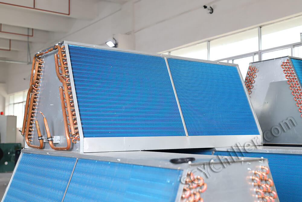
Nhiệt được truyền đến không khí xung quanh thông qua các cuộn dây có vây và quạt hướng trục hiệu suất cao. Hệ số truyền nhiệt cho thiết bị ngưng tụ làm mát bằng không khí thường là 30–100 W/m2·K.
| tham số | Giá trị điển hình | Xem xét thiết kế |
| Hệ số truyền nhiệt phía không khí | 30–100 W/m2·K | Hình dạng vây, tốc độ luồng khí |
| Vận tốc mặt | 2–4 m/s | Cân bằng truyền nhiệt và tiếng ồn |
| Phương pháp tiếp cận nhiệt độ | 8–15°C | Nhiệt độ ngưng tụ - nhiệt độ môi trường |
| Công suất giảm ở môi trường xung quanh cao | 3–5%/°C trên 35°C | Quan trọng đối với khí hậu nóng |
| Tiêu thụ điện năng của quạt | 0Làm mát 0,02–0,05 kW/kW | Đáng kể khi tải một phần |
Trong môi trường bán dẫn, hệ thống làm mát bằng không khí bị hạn chế bởi:
- Biến động nhiệt độ môi trường xung quanh: Sự dao động hàng ngày từ 10–20°C có thể ảnh hưởng đến áp suất ngưng tụ
- Hệ số truyền nhiệt thấp hơn: Yêu cầu diện tích bề mặt lớn hơn và công suất quạt cao hơn
- Nhạy cảm với tắc nghẽn luồng không khí: Bụi bẩn tích tụ làm giảm công suất 5–15% mỗi năm
- Tạo tiếng ồn: Tiếng ồn của quạt thường là 65–80 dB(A) ở 1 mét
Bình ngưng làm mát bằng nước
Water-cooled systems use a secondary water loop to reject heat through a cooling tower or dry cooler. The heat transfer coefficient for water-cooled condensers is typically 1000–6000 W/m²·K, approximately 25–50× higher than air.
| tham số | Giá trị điển hình | Advantage vs. Air-Cooled |
| Water-side heat transfer coefficient | 3000–6000 W/m²·K | 50–100× higher than air |
| Overall U-value | 1000–2500 W/m²·K | Compact design possible |
| Phương pháp tiếp cận nhiệt độ | 3–8°C | Lower condensing temperature |
| Condensing temperature (typical) | 32–38°C | 8–12°C lower than air-cooled |
| COP improvement | 15–25% | Lower compression ratio |
| Water consumption (cooling tower) | 1.5–2.0 L/h per kW | Requires water treatment |
Technically, water-cooled systems provide:
- Higher thermal conductivity of water: ~0,6 W/m·K so với ~0,026 W/m·K đối với không khí
- Nhiệt độ ngưng tụ ổn định hơn: Nước trong tháp thường thay đổi ±2–3°C so với ±10–20°C đối với không khí xung quanh
- COP tốt hơn: 4,5–6,5 so với 3,0–4,5 đối với làm mát bằng không khí ở điều kiện tương đương
- Tách rời khỏi sự biến đổi của môi trường xung quanh: Hiệu suất không phụ thuộc vào điều kiện ngoài trời
Trong các nhà máy tiên tiến, cấu hình làm mát bằng nước chiếm ưu thế cho các ứng dụng làm mát chính xác.
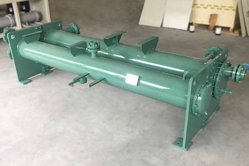
Thiết bị bay hơi (Lõi trao đổi nhiệt sơ cấp)
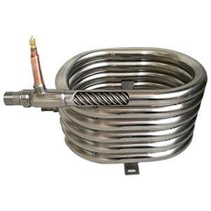
Thiết bị bay hơi là nơi nhiệt được hấp thụ từ vòng lặp quy trình. Trong thiết bị làm lạnh vòng kín bán dẫn, bộ trao đổi nhiệt tấm hàn (BPHE) thường được sử dụng do:
- Tỷ lệ diện tích bề mặt trên thể tích cao: 200–500 m2/m³, cao hơn 3–5× so với vỏ và ống
- Thiết kế tản nhiệt nhỏ gọn: Dấu chân 20–30% vỏ và ống tương đương
- Hiệu suất truyền nhiệt cao: Giá trị U 3000–7000 W/m2·K
- Phí làm lạnh thấp: Ít hơn 30–50% so với loại vỏ và ống, giảm tác động đến môi trường
Phân tích truyền nhiệt bay hơi:
Q.trốn tránh = U × A × LMTD
Ở đâu:
• U = Hệ số truyền nhiệt tổng thể (W/m2·K)
• A = Diện tích truyền nhiệt (m2)
• LMTD = Nhật ký chênh lệch nhiệt độ trung bình (°C)
LMTD cho dòng chảy ngược:
LMTD = (ΔT1 – ΔT2) / ln(ΔT1 / ΔT2)
| tham số | Đặc điểm kỹ thuật | Tác động đến hiệu suất |
| Hệ số phía môi chất lạnh | 5000–10000 W/m2·K | Điện trở truyền nhiệt sơ cấp |
| Hệ số phía chất lỏng xử lý | 4000–8000 W/m2·K | Phụ thuộc vào tốc độ dòng chảy và độ nhớt |
| Overall U-value | 3000–7000 W/m2·K | Khả năng chịu nhiệt kết hợp |
| Tiếp cận nhiệt độ | 1–3°C | Thấp hơn = hiệu quả cao hơn nhưng diện tích lớn hơn |
| Giảm áp suất (phía quá trình) | 20–80 kPa | Ảnh hưởng đến kích thước máy bơm |
| Quá nhiệt (thoát) | 5–8°C | Đảm bảo bay hơi hoàn toàn |
Bên trong thiết bị bay hơi:
- Chất làm lạnh hấp thụ nhiệt và bay hơi: Chuyển pha từ hỗn hợp lỏng-hơi sang hơi bão hòa/quá nhiệt
- Chất lỏng xử lý (hỗn hợp nước DI hoặc glycol) được làm mát gián tiếp: Không có tiếp xúc trực tiếp giữa chất làm lạnh và chất lỏng xử lý
- Tách nhiệt đảm bảo hoạt động không bị nhiễm bẩn: Quan trọng đối với các yêu cầu về độ tinh khiết của chất bán dẫn
Thiết bị bay hơi rất quan trọng vì ngay cả sự tắc nghẽn nhỏ hoặc mất cân bằng dòng chảy cũng có thể gây ra sự chênh lệch nhiệt độ. Đối với thiết bị bay hơi 100 kW với cách tiếp cận 5°C:
Tác động bám bẩn lên quá trình truyền nhiệt:
1/Ubị phạm lỗi = 1/Ulau dọn + Rf
Ở đâu Rf = hệ số bám bẩn (m2·K/W)
Ví dụ: rf = 0,0001 m2·K/W (điển hình cho nước DI)
bạnlau dọn = 5000 W/m2·K → Ubị phạm lỗi = 3333 W/m2·K
Kết quả: giảm 33% khả năng truyền nhiệt
Hệ thống bơm (Kiểm soát ổn định dòng chảy)
Hệ thống bơm xác định cách vận chuyển năng lượng nhiệt giữa máy làm lạnh và thiết bị bán dẫn. Không giống như các hệ thống công nghiệp tiêu chuẩn, làm mát chất bán dẫn yêu cầu:
- Kiểm soát dòng chảy ổn định cao: Độ ổn định tốc độ dòng chảy trong phạm vi ±1–2%
- Nhịp đập tối thiểu: <2% xung áp suất để tránh truyền rung
- Kết hợp dòng chảy chính xác với nhu cầu công cụ: Phản ứng động đối với những thay đổi của tải trong vòng vài giây
- Khả năng tương thích độ tinh khiết cực cao: Không gây ô nhiễm cho chất lỏng xử lý
Phương trình truyền nhiệt:
Q = ṁ × CP × ΔT
Ở đâu:
• Q = Tải nhiệt (kW)
• ṁ = Tốc độ dòng chảy lớn (kg/s)
• CP = Nhiệt dung riêng (kJ/kg·K)
• ΔT = Chênh lệch nhiệt độ (°C)
Đối với nước DI: CP ≈ 4,18 kJ/kg·K
Độ nhạy tốc độ dòng chảy: Biến đổi dòng chảy 10% → biến đổi truyền nhiệt ~8%
(ở mức không đổi ΔT, giả sử dòng chảy rối)
| Loại máy bơm | Phạm vi dòng chảy | Cái đầu | Nhịp đập | Loại con dấu | Ứng dụng |
| Ly tâm (Ổ đĩa từ) | 10–500 L/phút | 10–50 m | <2% | không bịt kín | Độ chính xác tiêu chuẩn |
| Ly tâm (Động cơ đóng hộp) | 10–300 L/phút | 10–40 m | <1% | không bịt kín | Độ tinh khiết cực cao |
| Ly tâm nhiều tầng | 50–1000 L/phút | 30–100 m | <3% | Cơ khí/Mag | Hệ thống áp suất cao |
| Tốc độ thay đổi (VFD) | Phạm vi 5–100% | Biến | <2% | Nhiều | Kết hợp tải động |
Hầu hết các hệ thống tiên tiến đều sử dụng:
- Bơm dẫn động từ: Thiết kế không bịt kín giúp loại bỏ nguy cơ ô nhiễm do rò rỉ phốt; MTBF điển hình >50.000 giờ
- Bơm tần số thay đổi: Flow adjustment range of 5–100% with response time <5 seconds
- Redundant pump configurations: N+1 or 2N for critical applications
Flow stability is directly linked to temperature stability because:
Temperature Stability vs. Flow Stability:
ΔTstability = f(Δṁ, ΔTmáy làm lạnh, thermal mass)
For a typical wafer tool with 50 kW load and 5°C ΔT:
• Required flow: ṁ = Q / (CP × ΔT) = 50 / (4.18 × 5) = 2.4 kg/s ≈ 144 L/min
• ±1% flow variation → ±0.05°C temperature variation at tool
• ±2% flow variation → ±0.1°C temperature variation at tool
Van giãn nở (Điều chỉnh môi chất lạnh chính xác)
The expansion valve controls refrigerant flow into the evaporator, maintaining proper superheat and optimizing evaporator utilization.
| Kiểu | Control Resolution | Response Time | Kiểm soát quá nhiệt | Ứng dụng |
| Thermostatic (TXV) | Continuous (mechanical) | 30–60 seconds | ±2–4°C | Standard industrial |
| Electronic (EEV) | 1–5% steps | 5–15 seconds | ±0,5–1,0°C | Precision chillers |
| Electronic (Stepper) | 0.5–2% steps | 2–5 seconds | ±0,3–0,5°C | Ultra-precision |
In wafer-grade systems, electronic expansion valves (EEV) are standard. Unlike mechanical valves, EEVs allow:
- Micro-level flow adjustment: Resolution of 0.5–2% of full stroke
- Fast response to load changes: 2–15 seconds vs. 30–60 seconds for TXV
- Stable superheat control: ±0.3–1.0°C vs. ±2–4°C for TXV
- Reduced temperature oscillation: Tác động trực tiếp đến sự ổn định nhiệt độ của quá trình
- Thuật toán điều khiển thích ứng: Tích hợp với PLC máy làm lạnh để điều khiển dự đoán
Tầm quan trọng của việc kiểm soát quá nhiệt:
SH = Thút – Tđã ngồi(Phút)
Ở đâu:
• SH = Quá nhiệt (°C)
• Thút = Nhiệt độ hút thực tế
• Tđã ngồi = Nhiệt độ bão hòa ở áp suất hút
Phạm vi quá nhiệt tối ưu: 5–8°C
• Quá thấp: Nguy cơ chất làm lạnh dạng lỏng quay trở lại máy nén (hư hỏng)
• Quá cao: Giảm hiệu suất thiết bị bay hơi (mất 10–20% công suất khi SH vượt quá 5°C)
Hệ thống điều khiển (Lớp thông minh nhiệt)
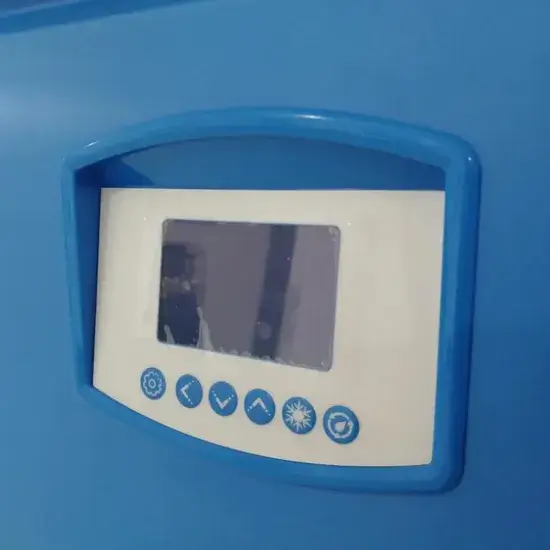
Hệ thống điều khiển là “bộ não” của máy làm lạnh vòng kín, điều phối tất cả các hệ thống con để đạt được khả năng kiểm soát nhiệt chính xác.
Kiến trúc điều khiển PID
Thuật toán điều khiển PID:
u(t) = KP × e(t) + KTôi × ∫e(t)dt + Kd × de(t)/dt
Ở đâu:
• u(t) = Đầu ra điều khiển (tần số máy nén, vị trí van)
• e(t) = Lỗi = Điểm đặt – Biến quy trình
• KP = Mức tăng tỷ lệ
• KTôi = Độ lợi tích phân
• Kd = Lãi phái sinh
| tham số | Phạm vi điển hình | Tác dụng | Hướng dẫn điều chỉnh |
| Dải tỷ lệ | 00,2–1,0°C | Tốc độ phản hồi | Nhỏ hơn = nhanh hơn nhưng có nguy cơ dao động |
| Thời gian tích phân (TTôi) | 20–120 giây | Loại bỏ phần bù | Ngắn hơn = loại bỏ bù đắp nhanh hơn |
| Thời gian đạo hàm (Td) | 0–30 giây | Dao động giảm chấn | Cao hơn = giảm xóc nhiều hơn |
| Thời gian mẫu | 00,1–1,0 giây | Tần số điều khiển | Nhanh hơn cho các ứng dụng chính xác |
| Giới hạn đầu ra | 15–100% (máy nén) | Ngăn ngừa bão hòa | Dựa trên tốc độ tối thiểu của máy nén |
Tính năng điều khiển nâng cao
Máy làm lạnh bán dẫn hiện đại sử dụng hệ thống vi điều khiển nhúng hoặc dựa trên PLC có khả năng:
- Kiểm soát nhiệt độ PID: Vòng điều khiển chính có điều chỉnh thích ứng
- Vòng phản hồi đa cảm biến: Cảm biến PT100 hoặc PT1000 dự phòng có logic biểu quyết
- Dự đoán tải thời gian thực: Điều khiển tiến tiến dựa trên tín hiệu quá trình
- Điều chế tần số máy nén: Điều khiển biến tần với dải công suất 15–100%
- Cân bằng dòng chảy qua nhiều vòng: Kiểm soát độc lập nhiều vùng quy trình
- Kiểm soát tầng: Vòng sơ cấp (nhiệt độ xử lý) → Vòng thứ cấp (nhiệt độ bay hơi)
- Cảm biến nhiệt độ dự phòng: PT100/PT1000 với cấu hình 4 dây, độ chính xác ±0,1°C
- Mô hình nhiệt đôi kỹ thuật số: Mô phỏng thời gian thực để điều khiển dự đoán
- Thuật toán dự đoán lỗi: Phát hiện bất thường dựa trên máy học
- Giao diện GIÂY/GEM: Tiêu chuẩn truyền thông thiết bị bán dẫn để tích hợp fab
- Remote monitoring and diagnostics: IoT connectivity for predictive maintenance
The goal is not just control, but predictive stabilization of thermal behavior, anticipating load changes before they affect process temperature.
Đặc tính tải nhiệt trong thiết bị wafer
Wafer processing equipment generates heat in highly dynamic and localized ways. Understanding these characteristics is essential for proper chiller sizing and control system design.
Cấu hình tải động
Unlike traditional industrial systems, semiconductor tools often have:
- Rapid thermal cycling: Load changes of 50–100% within 1–10 seconds
- Localized heat zones: Multiple independent thermal zones within one tool
- Pulsed heat loads: RF plasma, laser pulses with millisecond to second duration
- High sensitivity to return temperature: Process stability depends on inlet temperature
| Equipment | Typical Heat Load | Load Profile | Response Time Required | Temp Stability |
| Etch Chamber (RF Plasma) | 5–30 kW | Pulsed (RF on/off) | <5 seconds | ±0,1–0,2°C |
| CVD Reactor | 10–50 kW | Step changes (recipe) | <10 seconds | ±0,1–0,3°C |
| Lithography Scanner | 20–100 kW | Steady + transients | <2 seconds | ±0.01–0.05°C |
| Ion Implanter | 10–40 kW | Pulsed (beam on/off) | <5 seconds | ±0,1–0,2°C |
| Laser System | 2–15 kW | Pulsed (ms to s) | <1 second | ±0,05–0,1°C |
| Electrostatic Chuck (ESC) | 1–5 kW | Variable (process) | <10 seconds | ±0,05–0,1°C |
| Vacuum Pump | 1–10 kW | Steady state | <30 seconds | ±0,5–1,0°C |
Phân tích nguồn nhiệt
Typical heat sources in wafer processing equipment include:
| Heat Source | Cơ chế | Typical Power Density | Phương pháp làm mát |
|---|---|---|---|
| RF Plasma Generators | Ion bombardment, joule heating | 0.5–5 W/cm² | Direct cooling, ESC |
| Laser Systems (excimer, solid-state) | Optical absorption, waste heat | 1–10 W/cm² (localized) | Optics cooling, laser head |
| Vacuum Pumps (turbo, dry) | Friction, compression heat | 0.1–0.5 W/cm² | Jacket cooling |
| Electrostatic Chucks (ESC) | RF coupling, helium backside | 0.1–2 W/cm² | Internal channels |
| Chemical Reaction Chambers | Exothermic reactions, plasma | 0.5–3 W/cm² | Chamber walls, showerhead |
| Heater Elements | Resistive heating | 5–50 W/cm² | Process temperature control |
Because of this variability, closed loop chillers must respond quickly and maintain stable output under fluctuating loads. Key design considerations include:
- Thermal mass: Buffer tanks to dampen temperature fluctuations
- Fast-responding control: EEV and VFD compressor for rapid capacity adjustment
- Multi-zone capability: Independent temperature control for different process zones
Yêu cầu về độ chính xác trong làm mát chất bán dẫn
Wafer processing tools require significantly higher precision than most industrial applications. The temperature stability requirement is driven by the thermal expansion coefficient of silicon and the feature sizes being manufactured.
Thermal Expansion Impact on Overlay Error:
ΔL = α × L × ΔT
Ở đâu:
• ΔL = Length change (nm)
• α = Thermal expansion coefficient (2.6×10⁻⁶/°C for Si)
• L = Wafer diameter (mm)
• ΔT = Temperature change (°C)
Example for 300 mm wafer:
ΔT = 0.1°C → ΔL = 2.6×10⁻⁶ × 300 × 0.1 = 78 nm
For 7 nm node with 3 nm overlay budget:
Required ΔT < 0.01°C to stay within overlay tolerance
Yêu cầu về độ ổn định nhiệt độ theo ứng dụng
| Ứng dụng | Ổn định nhiệt độ | Setpoint Range | Control Resolution | Sensor Accuracy |
|---|---|---|---|---|
| General industrial cooling | ±1,0°C | 5–35°C | 0.1°C | ± 0,5°C |
| Advanced manufacturing tools | ± 0,5°C | 10–30°C | 0.05°C | ±0,2°C |
| Semiconductor wafer processing | ±0,1–0,2°C | 15–25°C | 0.01°C | ±0,05°C |
| Critical lithography systems | ±0.01–0.05°C | 20–23°C | 0.001°C | ±0.01°C |
| EUV scanner optics | ±0.005–0.01°C | 22–24°C | 0.0005°C | ±0.005°C |
Yêu cầu thiết kế hệ thống để làm mát chính xác
Achieving sub-0.1°C temperature stability requires:
- High-resolution temperature sensors: PT100 or PT1000 with 4-wire configuration, resolution 0.001–0.01°C
- PID or advanced predictive control: Adaptive tuning, feedforward compensation
- Variable frequency compressor control: 15–100% capacity modulation with <1% speed resolution
- Precise flow regulation: VFD pumps with <1% flow stability
- Low thermal inertia system design: Minimized fluid volume for fast response
- Thermal buffer tanks: De-couples chiller dynamics from process transients
- Multi-stage cooling architecture: Primary + secondary precision loop for critical applications
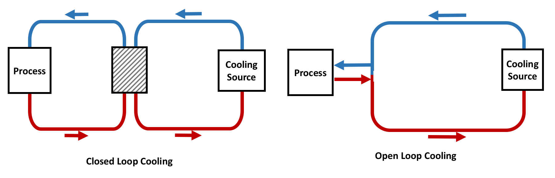
Tại sao máy làm lạnh vòng kín hoạt động tốt hơn hệ thống mở
Lợi thế ổn định nhiệt
Closed loop systems have significantly lower thermal fluctuation because:
- No direct environmental exposure: Process fluid isolated from ambient conditions
- Controlled internal fluid volume: Known thermal mass for predictable response
- Stable heat exchange interface: Consistent heat transfer coefficients
- Precise water quality control: DI water resistivity >18 MΩ·cm maintained
| tham số | Closed Loop | Open Loop | Improvement |
| Ổn định nhiệt độ | ±0.05–0.2°C | ±0,5–2,0°C | 5–10× better |
| Thời gian đáp ứng | 5–30 seconds | 30–120 seconds | 2–4× faster |
| Water quality control | DI water, >18 MΩ·cm | Tower water, variable | Ultra-pure |
| Contamination risk | Very low | High (airborne, biological) | Significant |
| Biến đổi theo mùa | Tối thiểu | Significant | Decoupled from ambient |
Hiệu quả năng lượng ở mức tải ổn định
In semiconductor fabs, loads are relatively stable compared to industrial environments, allowing optimization for steady-state efficiency.
Energy Efficiency Metrics:
COP (Coefficient of Performance):
COP = Qlàm mát / Pinput
IPLV (Integrated Part Load Value):
IPLV = 0.01A + 0.42B + 0.45C + 0.12D
Where A, B, C, D = COP at 100%, 75%, 50%, 25% load
Typical Semiconductor Chiller:
• COP: 4.0–6.0 (water-cooled), 3.0–4.5 (air-cooled)
• IPLV: 5.0–7.0 (water-cooled), 3.5–5.0 (air-cooled)
Closed loop chillers optimize:
- Compressor cycling efficiency: VFD reduces cycling losses by 20–40%
- Hiệu suất tải một phần: IPLV typically 20–30% better than full-load COP
- Heat recovery potential: 60–80% of compressor work recoverable for facility heating
Giảm độ phức tạp bảo trì
Because the system is sealed:
- No cooling tower maintenance: Eliminates basin cleaning, drift elimination, fill replacement
- No water contamination control: No biological growth, algae, or Legionella risk
- Reduced corrosion risk: Closed system with controlled water chemistry
- Longer system lifespan: Typical 15–20 years vs. 10–15 years for open systems
- Lower water treatment costs: Minimal chemical consumption
This is especially important in 24/7 semiconductor fabs where maintenance windows are limited.
Tích hợp với thiết bị xử lý wafer
Closed loop chillers are commonly integrated with:
| Equipment Type | Yêu cầu làm mát | Typical Configuration | Interface Standard |
|---|---|---|---|
| Lithography Systems (DUV/EUV) | Optics, reticle, wafer stage, illumination | Multi-zone, ultra-precision | SECS/GEM, OPC-UA |
| Etching Tools (RIE, ICP, DRIE) | ESC, chamber walls, RF generator | Multi-loop, fast response | SECS/GEM |
| Deposition (CVD, PVD, ALD) | Chamber, showerhead, heater | Multi-zone, high capacity | SECS/GEM |
| Cấy ion | Beam line, target, analyzer | Multi-loop, precision | SECS/GEM |
| Metrology (CD-SEM, AFM) | Stage, optics, electronics | Single/multi-zone | Varies |
| Vacuum Processing | Pumps, chambers, gauges | Single loop, moderate precision | Varies |
Each system may require independent thermal control zones depending on process sensitivity. Advanced fabs often deploy multi-loop chiller architectures to support different temperature zones within the same production line.
Kiến trúc nhiệt đa vùng
| Zone | Tải nhiệt | Nhiệt độ | Stability | Fluid |
| Electrostatic Chuck (ESC) | 2–5 kW | -20 to +80°C | ±0,1°C | DI water/glycol |
| Chamber Walls | 3–8 kW | 20–40°C | ± 0,5°C | DI water |
| RF Generator | 1–3 kW | 20–30°C | ±1,0°C | DI water |
| Vacuum Pump | 1–2 kW | 20–40°C | ±2.0°C | DI water |
| Total | 7–18 kW | — | — | — |
Dự phòng trong hệ thống làm mát bán dẫn
In semiconductor manufacturing, downtime is extremely costly. A single thermal interruption may result in:
- Wafer batch loss: $50,000–$500,000+ per lot depending on product
- Process instability: Hours to days of re-qualification
- Tool recalibration requirements: 4–24 hours of lost production
- Production delays: Ripple effects through fab schedule
Tùy chọn kiến trúc dự phòng
| Cấu hình | Sự miêu tả | Availability | Cost Premium | Ứng dụng |
| N+1 | One backup unit for N operating units | 99.5–99.9% | +15–25% | Standard production |
| 2N | Fully redundant (100% backup) | 99.9–99.99% | +80–100% | Critical tools |
| 2N+1 | Fully redundant with spare | 99.99%+ | +100–120% | Ultra-critical (EUV) |
| Dual Loop | Two independent cooling loops per tool | 99.9%+ | +50–70% | Multi-zone tools |
Closed loop chiller systems are often designed with:
- Dự phòng N+1: One standby chiller for every N operating chillers
- Dual pump systems: Automatic switchover on pump failure
- Backup compressor modules: Quick-change compressor cartridges
- Parallel cooling loops: Independent loops for critical zones
- UPS for control systems: Uninterruptible power for controls and sensors
Hệ thống chuyển mạch tự động
Modern redundant systems include automatic switchover capability:
- Temperature deviation trigger: Switchover when temperature exceeds ±0.2°C from setpoint
- Flow deviation trigger: Switchover when flow drops below 90% of setpoint
- Equipment fault trigger: Switchover on compressor, pump, or sensor fault
- Switchover time: <30 seconds to maintain process continuity
Phần kết luận
Closed loop chillers play a foundational role in modern wafer processing equipment by providing ultra-stable, contamination-free, and highly precise temperature control.
Key technical advantages of closed loop systems for semiconductor manufacturing:
- Thermal stability: ±0.05–0.2°C achievable, 5–10× better than open systems
- Contamination control: DI water quality >18 MΩ·cm maintained throughout system
- Process repeatability: Consistent thermal conditions enable high yield manufacturing
- Hiệu suất năng lượng: COP of 4.0–6.0 with VFD compressors and optimized control
- độ tin cậy: 15–20 year system lifetime with proper maintenance
Critical design considerations for semiconductor chillers:
- Compressor selection: Inverter-driven scroll or screw for modulation stability
- Evaporator design: Brazed plate for high efficiency and low refrigerant charge
- Control system: PID with adaptive tuning, feedforward, and predictive capabilities
- Dự phòng: N+1 or 2N configuration for critical applications
- Tích hợp: SECS/GEM interface for fab automation
As semiconductor technology continues to advance toward smaller nodes (<5 nm) and new architectures (GAA, chiplets), closed loop cooling systems will become even more critical in supporting next-generation wafer fabrication. The thermal precision requirements will tighten to ±0.01°C or better for critical processes, demanding continued innovation in:
- Ultra-precision temperature control algorithms
- Low-thermal-inertia system designs
- Multi-zone independent thermal management
- AI-based predictive thermal control
- Sustainable refrigerant and energy technologies
Ultimately, thermal precision directly determines yield, device performance, and manufacturing success in advanced semiconductor fabrication.