
O processamento de wafer é um dos ambientes de fabricação mais sensíveis termicamente na indústria moderna. Ao contrário do resfriamento industrial convencional, o controle de temperatura dos semicondutores opera em uma escala onde fidelidade de padrão em nível nanométrico, gravar uniformidade, e precisão de deposição podem ser influenciados por flutuações de temperatura tão pequenas quanto ±0,05°C.
Neste contexto, um chiller de circuito fechado não é simplesmente uma “máquina de refrigeração”. É um sistema de controle térmico de precisão integrado à arquitetura de processo de equipamentos de fabricação de wafers. Seu papel é manter condições térmicas ultraestáveis em ferramentas como sistemas de litografia, câmaras de gravação, reatores de deposição e plataformas de metrologia.
O desafio do controle térmico na fabricação de semicondutores é caracterizado por:
- Requisitos extremos de precisão: Estabilidade de temperatura geralmente entre ±0,05–0,1°C para processos críticos
- Perfis de carga dinâmicos: Ciclagem térmica rápida com constantes de tempo de segundos a minutos
- Gerenciamento térmico multizona: Controle independente de múltiplas zonas de temperatura em uma única ferramenta
- Requisitos de pureza ultra-alta: resistividade à água DI >18 MΩ·cm, contagem de partículas <1 por mL a 0,05 μm
Para entender por que os sistemas de circuito fechado são essenciais, é necessário analisar tanto a arquitetura do sistema quanto a física térmica por trás do processamento do wafer.
Por que o controle térmico é fundamental no processamento de wafers
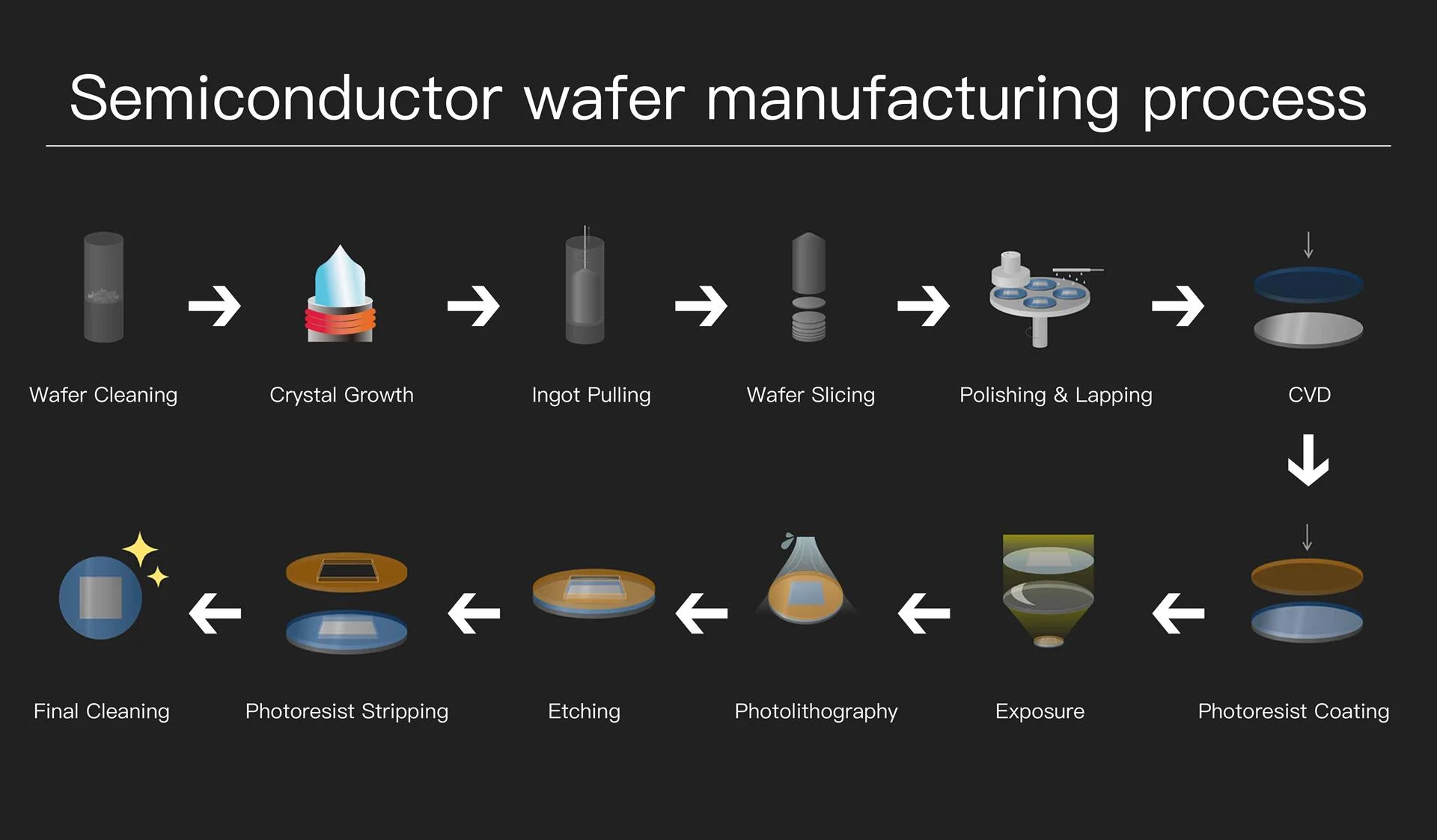
Os wafers semicondutores são fabricados com precisão em escala nanométrica. Neste nível, mesmo desvios térmicos extremamente pequenos podem levar a variações mensuráveis do processo através de múltiplos mecanismos:
Efeitos térmicos nos parâmetros do processo
| Processo | Mecanismo de efeito térmico | Sensibilidade à temperatura | Impacto do desvio de ±0,1°C |
|---|---|---|---|
| Fotolitografia (DUV/EUV) | Viscosidade fotorresistente, expansão de wafer | ±0,02 nm/°C (variação CD) | Deslocamento de CD: 0,2–0,5 nm |
| Gravura Plasmática | Taxa de gravação, seletividade, perfil | ±1–3%/°C (taxa de corrosão) | Variação de profundidade de gravação: 2–5 nm |
| Deposição de DCV | Cinética de reação, estresse do filme | ±2–5%/°C (taxa de deposição) | Não uniformidade de espessura: 0,5–1% |
| Processamento úmido | Taxa de reação química, difusão | ±5–10%/°C (taxa de reação) | Variação da taxa de gravação: 5–10% |
| Implantação Iônica | Estabilidade do feixe, carregamento de wafer | ±0,5%/°C (uniformidade da dose) | Variação de dose: 0,1–0,3% |
A temperatura afeta diretamente:
- Comportamento fotorresistente durante a litografia: Mudanças de viscosidade de 2–3% por °C afetam a uniformidade do revestimento giratório; expansão térmica do silício (α = 2,6×10⁻⁶/°C) causa erros de sobreposição
- Consistência da taxa de gravação: A relação de Arrhenius governa as taxas de reação química; energia de ativação típica de 0,3–0,8 eV resulta em sensibilidade de 2–5%/°C
- Uniformidade de deposição de filme fino: Cinética da reação de superfície e química da fase gasosa, ambas dependentes da temperatura
- Estabilidade de reação química em processos úmidos: Seletividade de ataque e rugosidade superficial afetada pela temperatura
- Precisão dimensional em escala micro e nano: A expansão térmica do wafer e do mandril afeta o registro
Requisitos de estabilidade de temperatura por nó de processo
| Nó de Tecnologia | Tamanho do recurso | Estabilidade da temperatura | Orçamento Térmico | Aplicações Típicas |
| 28nm e acima | ≥28nm | ±0,2–0,5°C | Menos crítico | Lógica geral, analógica |
| 14–20 nm | 14–20 nm | ±0,1–0,2°C | Moderado | FinFET, lógica avançada |
| 7–10nm | 7–10nm | ±0,05–0,1°C | Crítico | FinFET avançado |
| 5 nm e abaixo | ≤5nm | ±0,02–0,05°C | Extremamente crítico | GAA, nós avançados |
| Litografia EUV | 7nm e abaixo | ±0,01–0,02°C | Ultracrítico | Óptica do scanner, retículo |
Neste nível de precisão, os sistemas de refrigeração convencionais são insuficientes e os sistemas de refrigeração em circuito fechado tornam-se essenciais.
Termodinâmica da refrigeração por compressão de vapor
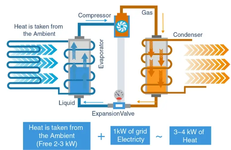
Compreender a base termodinâmica dos chillers de circuito fechado é essencial para a especificação e otimização adequadas do sistema.
Análise do Ciclo Pressão-Entalpia (P-h)
O ciclo de refrigeração por compressão de vapor pode ser analisado em um diagrama P-h, mostrando quatro processos distintos:
Ciclo Ideal de Compressão de Vapor (Condições de Classificação Padrão):
Processo 1→2 (Compressão Isentrópica):
Ccomparação = ṁ × (h2 –h1)
Processo 2→3 (Condensação Isobárica):
Qcondição = ṁ × (h2 –h3)
Processo 3→4 (Expansão Isentálpica):
h3 =h4 (estrangulamento, sem trabalho)
Processo 4→1 (Evaporação Isobárica):
Qevaporar = ṁ × (h1 –h4)
Coeficiente de Desempenho:
COP = Qevaporar / Ccomparação = (h1 –h4) / (h2 –h1)
Seleção de refrigerante para resfriadores semicondutores
| Refrigerante | GWP | ODP | Tcrítico | Pevaporar @ -10°C | Pcondição @ 40°C | Inscrição |
| R-134a | 1430 | 0 | 101,1ºC | Barra 2,0 | 10,2 barras | Precisão padrão |
| R-410A | 2088 | 0 | 71,4°C | 6,2 barras | 24,2 barras | Alta capacidade |
| R-407C | 1774 | 0 | 86,2ºC | 3,5 barras | 16,5 barras | Aplicações de modernização |
| R-1234ze | 1 | 0 | 109,4°C | 1,4 barra | 7,4 barras | Baixo GWP, novos designs |
| R-513A | 573 | 0 | 96,5ºC | 1,8 barra | 9,5 barras | Substituição do R-134a |
Para aplicações de semicondutores, a seleção do refrigerante considera:
- Deslizamento de temperatura: Misturas zeotrópicas (R-407C) apresentam deslizamento de temperatura durante a mudança de fase, afetando a precisão do controle
- Razão de pressão: Taxas de pressão mais baixas reduzem o trabalho do compressor e melhoram a eficiência
- Conformidade ambiental: Regulamentos da UE sobre gases fluorados e requisitos do programa SNAP da EPA
- Compatibilidade de materiais: Óleos POE para refrigerantes HFC, compatibilidade com vedações e juntas
Arquitetura do sistema de resfriamento de circuito fechado
Um chiller de circuito fechado de classe semicondutora é composto por vários subsistemas interdependentes. Cada um desempenha um papel distinto na obtenção da precisão térmica.
Sistema Compressor (Driver de Energia Térmica)
O compressor é o principal componente de conversão de energia do chiller. Ele converte vapor refrigerante de baixa pressão em vapor de alta pressão e alta temperatura, permitindo a rejeição de calor no estágio do condensador.
| Tipo | Faixa de capacidade | Modulação | Eficiência em carga parcial | Estabilidade da temperatura | Melhor Aplicação |
| Rolar (fixo) | 3–50 kW | Ligado/Desligado | Ruim em <50% | ±0,5–1,0°C | Auxiliar não crítico |
| Rolar (inversor) | 3–70 kW | 15–100% | Excelente | ±0,1–0,3°C | A maioria dos chillers de precisão |
| Parafuso (fixo) | 50–500 kW | Etapa (25/50/75/100%) | Moderado | ±0,3–0,5°C | Grandes plantas centrais |
| Parafuso (VFD) | 50–500 kW | 25–100% | Excelente | ±0,1–0,3°C | Grandes sistemas de precisão |
| Centrífuga | 200–2000 kW | Palhetas + VFD | Bom | ±0,2–0,4°C | Resfriamento de instalações centrais |
Nos chillers de processamento de wafer, o principal requisito técnico não é apenas a capacidade, mas estabilidade de modulação. Os sistemas modernos usam inversores de frequência variável (VFDs) para manter:
- Pressão de sucção estável: Normalmente mantido dentro de ±0,1 bar do ponto de ajuste
- Overshoot térmico reduzido: ultrapassagem de <0,3°C em mudanças de carga vs. 2–5°C para controle liga/desliga
- Adaptação suave à carga: Tempo de resposta <10 segundos para mudança de etapa de carga de 50%
- Ciclismo mínimo: Partidas reduzidas de 10–20/hora para 2–4/hora
Potência do compressor versus frequência (unidade inversora):
Pcomparação ∝ (f/favaliado)³ × Pavaliado
Onde:
• f = Frequência operacional (Hz)
• favaliado = Frequência nominal (normalmente 50 ou 60 Hz)
•Pavaliado = Potência nominal em velocidade máxima
Aplicação da Lei de Afinidade: 50% de velocidade → ~12,5% de potência (teórico)
Sem esta modulação, a oscilação de temperatura se propagaria diretamente para a instabilidade do processamento do wafer, causando potencialmente:
- Variação da dimensão crítica (CD) na litografia
- Gravar não uniformidade de profundidade no wafer
- Variação da espessura do filme em processos de deposição
Sistema Condensador (Interface de Rejeição de Calor)
O condensador é responsável pela transferência de calor do refrigerante para o ambiente externo. A capacidade do condensador deve ser dimensionada para rejeitar tanto a carga de calor do evaporador quanto o trabalho do compressor:
Rejeição de calor do condensador:
Qcondição =Qevaporar + Wcomparação
Para chillers semicondutores típicos:
Qcondição ≈ 1,2–1,4 × Qevaporar (dependendo da COP)
Condensadores resfriados a ar
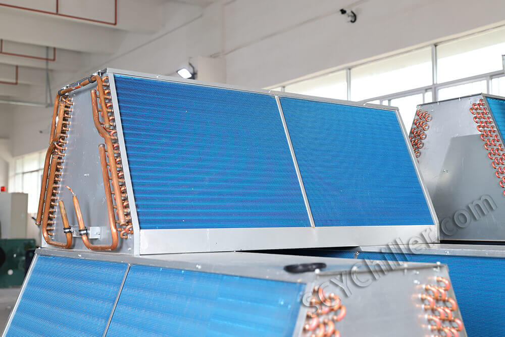
O calor é transferido para o ar ambiente através de serpentinas aletadas e ventiladores axiais de alta eficiência. O coeficiente de transferência de calor para condensadores resfriados a ar é normalmente 30–100 W/m²·K.
| Parâmetro | Valor típico | Consideração de projeto |
| Coeficiente de transferência de calor do lado do ar | 30–100 W/m²·K | Geometria da aleta, taxa de fluxo de ar |
| Velocidade facial | 2–4m/s | Equilibra a transferência de calor e o ruído |
| Abordagem de temperatura | 8–15°C | Temperatura de condensação – temperatura ambiente |
| Redução de capacidade em ambiente alto | 3–5%/°C acima de 35°C | Crítico para climas quentes |
| Consumo de energia do ventilador | 00,02–0,05 kW/kW de resfriamento | Significativo em carga parcial |
Em ambientes semicondutores, os sistemas refrigerados a ar são limitados por:
- Flutuações de temperatura ambiente: Oscilações diárias de 10–20°C podem afetar a pressão de condensação
- Menor coeficiente de transferência de calor: Requer maior área de superfície e maior potência do ventilador
- Sensibilidade à obstrução do fluxo aéreo: O acúmulo de sujeira reduz a capacidade em 5–15% ao ano
- Geração de ruído: Ruído do ventilador normalmente 65–80 dB(A) a 1 metro
Condensadores resfriados a água
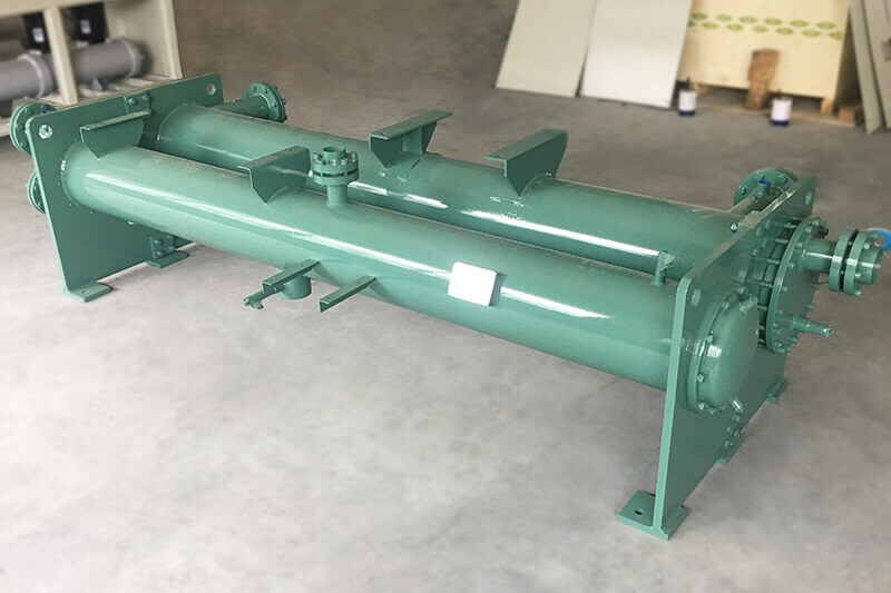
Os sistemas resfriados a água usam um circuito secundário de água para rejeitar o calor através de uma torre de resfriamento ou refrigerador seco. O coeficiente de transferência de calor para condensadores resfriados a água é normalmente 1000–6000 W/m²·K, aproximadamente 25–50× mais alto que o ar.
| Parâmetro | Valor típico | Vantagem vs. Refrigerado a Ar |
| Coeficiente de transferência de calor do lado da água | 3.000–6.000 W/m²·K | 50–100× mais alto que o ar |
| Valor U geral | 1000–2500 W/m²·K | Design compacto possível |
| Abordagem de temperatura | 3–8°C | Temperatura de condensação mais baixa |
| Temperatura de condensação (típica) | 32–38°C | 8–12°C mais baixo que refrigerado a ar |
| Melhoria do COP | 15–25% | Taxa de compressão mais baixa |
| Consumo de água (torre de resfriamento) | 1,5–2,0 L/h por kW | Requer tratamento de água |
Tecnicamente, os sistemas refrigerados a água fornecem:
- Maior condutividade térmica da água: ~0,6 W/m·K vs. ~0,026 W/m·K para ar
- Temperatura de condensação mais estável: A água da torre normalmente varia ±2–3°C vs. ±10–20°C para o ar ambiente
- Melhor COP: 4,5–6,5 vs. 3,0–4,5 para resfriado a ar em condições equivalentes
- Desacoplado da variabilidade ambiente: Desempenho independente das condições externas
Em fábricas avançadas, as configurações refrigeradas a água dominam para aplicações de refrigeração de precisão.
Evaporador (núcleo primário de troca de calor)
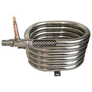
O evaporador é onde o calor é absorvido do circuito do processo. Em chillers de circuito fechado semicondutores, trocadores de calor de placas soldadas (BPHE) são comumente usados devido a:
- Alta relação área de superfície/volume: 200–500 m²/m³, 3–5× mais alto que casco e tubo
- Design térmico compacto: Pegada 20–30% do casco e tubo equivalente
- Alta eficiência de transferência de calor: Valores U de 3.000–7.000 W/m²·K
- Baixa carga de refrigerante: 30–50% menos que casco e tubo, reduzindo o impacto ambiental
Análise de transferência de calor do evaporador:
Qevaporar = U × A × LMTD
Onde:
• U = Coeficiente geral de transferência de calor (W/m²·K)
• A = Área de transferência de calor (m²)
• LMTD = Log da diferença média de temperatura (°C)
LMTD para contrafluxo:
LMTD = (ΔT1 –ΔT2) /ln(ΔT1 /ΔT2)
| Parâmetro | Especificação | Impacto no desempenho |
| Coeficiente do lado do refrigerante | 5.000–10.000 W/m²·K | Resistência primária à transferência de calor |
| Coeficiente do lado do fluido do processo | 4.000–8.000 W/m²·K | Depende da vazão e da viscosidade |
| Valor U geral | 3.000–7.000 W/m²·K | Resistência térmica combinada |
| Temperatura de aproximação | 1–3°C | Menor = maior eficiência, mas área maior |
| Queda de pressão (lado do processo) | 20–80kPa | Afeta o dimensionamento da bomba |
| Superaquecimento (saída) | 5–8°C | Garante evaporação completa |
Dentro do evaporador:
- O refrigerante absorve calor e evapora: Mudança de fase de mistura líquido-vapor para vapor saturado/superaquecido
- O fluido do processo (água deionizada ou mistura de glicol) é resfriado indiretamente: Sem contato direto entre o refrigerante e o fluido do processo
- A separação térmica garante uma operação livre de contaminação: Crítico para requisitos de pureza de semicondutores
O evaporador é crítico porque mesmo pequenas incrustações ou desequilíbrio de fluxo podem provocar desvios de temperatura. Para um evaporador de 100 kW com abordagem de 5°C:
Impacto de incrustação na transferência de calor:
1/Usujo = 1/Ulimpar +Rf
Onde Rf = fator de incrustação (m²·K/W)
Exemplo: Rf = 0,0001 m²·K/W (típico para água DI)
Vocêlimpar = 5000 W/m²·K → Usujo = 3333 W/m²·K
Resultado: redução de 33% na capacidade de transferência de calor
Sistema de Bombeamento (Controle de Estabilidade de Fluxo)
O sistema de bomba define como a energia térmica é transportada entre o chiller e o equipamento wafer. Ao contrário dos sistemas industriais padrão, o resfriamento de semicondutores requer:
- Controle de fluxo altamente estável: Estabilidade da taxa de fluxo dentro de ±1–2%
- Pulsação mínima: <2% de pulsação de pressão para evitar transmissão de vibração
- Correspondência precisa do fluxo à demanda da ferramenta: Resposta dinâmica para carregar alterações em segundos
- Compatibilidade com pureza ultra-alta: Sem introdução de contaminação no fluido do processo
Equação de transporte de calor:
Q = ṁ × Cp ×ΔT
Onde:
• Q = Carga térmica (kW)
• ṁ = vazão mássica (kg/s)
•Cp = Capacidade de calor específico (kJ/kg·K)
• ΔT = diferença de temperatura (°C)
Para água DI: Cp ≈ 4,18 kJ/kg·K
Sensibilidade da taxa de fluxo: 10% de variação de fluxo → ~8% de variação de transferência de calor
(em ΔT constante, assumindo fluxo turbulento)
| Tipo de bomba | Faixa de fluxo | Cabeça | Pulsação | Tipo de vedação | Inscrição |
| Centrífuga (unidade magnética) | 10–500 L/min | 10–50 metros | <2% | Sem selo | Precisão padrão |
| Centrífuga (motor enlatado) | 10–300 L/min | 10–40 metros | <1% | Sem selo | Pureza ultra-alta |
| Centrífuga multiestágio | 50–1000 L/min | 30–100 metros | <3% | Mecânico/Mag | Sistemas de alta pressão |
| Velocidade Variável (VFD) | Faixa de 5–100% | Variável | <2% | Vários | Correspondência dinâmica de carga |
Os sistemas mais avançados usam:
- Bombas de acionamento magnético: O design sem vedação elimina o risco de contaminação por vazamento da vedação; MTBF típico >50.000 horas
- Bombas de frequência variável: Faixa de ajuste de fluxo de 5–100% com tempo de resposta <5 segundos
- Configurações de bomba redundantes: N+1 ou 2N para aplicações críticas
A estabilidade do fluxo está diretamente ligada à estabilidade da temperatura porque:
Estabilidade de temperatura vs. estabilidade de fluxo:
ΔTestabilidade = f(Δṁ, ΔTresfriador, massa térmica)
Para uma ferramenta wafer típica com carga de 50 kW e 5°C ΔT:
• Fluxo necessário: ṁ = Q / (Cp × ΔT) = 50 / (4,18 × 5) = 2,4 kg/s ≈ 144 L/min
• Variação de vazão de ±1% → variação de temperatura de ±0,05°C na ferramenta
• Variação de vazão de ±2% → variação de temperatura de ±0,1°C na ferramenta
Válvula de Expansão (Regulação de Refrigerante de Precisão)
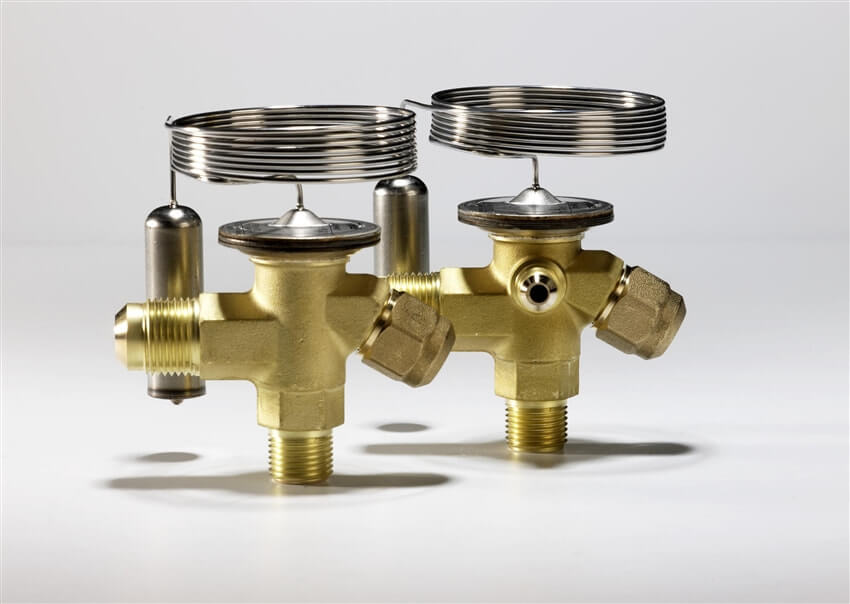
A válvula de expansão controla o fluxo de refrigerante no evaporador, mantendo o superaquecimento adequado e otimizando a utilização do evaporador.
| Tipo | Resolução de controle | Tempo de resposta | Controle de superaquecimento | Inscrição |
| Termostática (TXV) | Contínuo (mecânico) | 30–60 segundos | ±2–4°C | Industrial padrão |
| Eletrônico (EEV) | Etapas de 1–5% | 5–15 segundos | ±0,5–1,0°C | Chillers de precisão |
| Eletrônico (passo a passo) | 00,5–2% etapas | 2–5 segundos | ±0,3–0,5°C | Ultra-precisão |
Em sistemas wafer, as válvulas de expansão eletrônica (EEV) são padrão. Ao contrário das válvulas mecânicas, as EEVs permitem:
- Ajuste de fluxo de micronível: Resolução de 0,5–2% do curso completo
- Resposta rápida às alterações de carga: 2–15 segundos versus 30–60 segundos para TXV
- Controle estável de superaquecimento: ±0,3–1,0°C vs. ±2–4°C para TXV
- Oscilação de temperatura reduzida: Impacto direto na estabilidade da temperatura do processo
- Algoritmos de controle adaptativos: Integração com PLC do chiller para controle preditivo
Importância do controle de superaquecimento:
SH = Tsucção –Tsentado(Psucção)
Onde:
• SH = Superaquecimento (°C)
•Tsucção = Temperatura real de sucção
•Tsentado = Temperatura de saturação na pressão de sucção
Faixa ideal de superaquecimento: 5–8°C
• Muito baixo: Risco de retorno do refrigerante líquido ao compressor (danos)
• Muito alto: Eficiência reduzida do evaporador (10–20% de perda de capacidade por 5°C de excesso de SH)
Sistema de Controle (Camada de Inteligência Térmica)
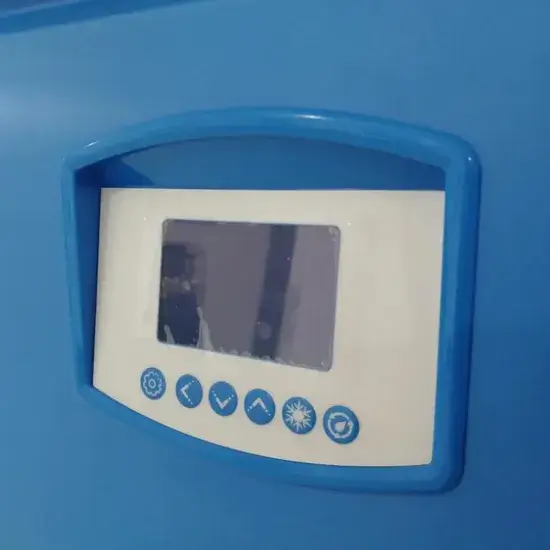
O sistema de controle é o “cérebro” do chiller de circuito fechado, coordenando todos os subsistemas para obter um controle térmico preciso.
Arquitetura de controle PID
Algoritmo de controle PID:
você(t) = Kp × e(t) + Keu × ∫e(t)dt + Kd × de(t)/dt
Onde:
• u(t) = Saída de controle (frequência do compressor, posição da válvula)
• e(t) = Erro = Setpoint – Variável do processo
• Kp = Ganho proporcional
• Keu = Ganho integral
• Kd = Ganho derivado
| Parâmetro | Faixa Típica | Efeito | Orientação de ajuste |
| Banda Proporcional | 00,2–1,0°C | Velocidade de resposta | Menor = mais rápido, mas risco de oscilação |
| Tempo Integral (Teu) | 20–120 segundos | Elimina deslocamento | Mais curto = eliminação mais rápida do deslocamento |
| Tempo Derivativo (Td) | 0–30 segundos | Oscilação de umidade | Maior = mais amortecimento |
| Tempo de amostragem | 00,1–1,0 segundos | Frequência de controle | Mais rápido para aplicações de precisão |
| Limitação de saída | 15–100% (compressor) | Evita a saturação | Com base na velocidade mínima do compressor |
Recursos de controle avançados
Os chillers semicondutores modernos usam sistemas microcontroladores baseados em PLC ou integrados, capazes de:
- Controle de temperatura PID: Malha de controle primário com sintonia adaptativa
- Loops de feedback multissensor: Sensores redundantes PT100 ou PT1000 com lógica de votação
- Previsão de carga em tempo real: Controle feedforward baseado em sinais de processo
- Modulação de frequência do compressor: Controle do inversor com faixa de capacidade de 15–100%
- Balanceamento de fluxo em vários loops: Controle independente de múltiplas zonas de processo
- Controle em cascata: Loop primário (temperatura do processo) → Loop secundário (temperatura do evaporador)
- Sensores de temperatura redundantes: PT100/PT1000 com configuração de 4 fios, precisão ±0,1°C
- Modelagem térmica dupla digital: Simulação em tempo real para controle preditivo
- Algoritmos de previsão de falhas: Detecção de anomalias baseada em aprendizado de máquina
- Interface SECS/GEM: Padrão de comunicação de equipamentos semicondutores para integração fabril
- Monitoramento e diagnóstico remoto: Conectividade IoT para manutenção preditiva
O objetivo não é apenas o controle, mas a estabilização preditiva do comportamento térmico, antecipando mudanças de carga antes que afetem a temperatura do processo.
Características de carga térmica em equipamentos wafer
Equipamentos de processamento de wafer geram calor de maneiras altamente dinâmicas e localizadas. Compreender essas características é essencial para o dimensionamento adequado do chiller e o projeto do sistema de controle.
Perfis de carga dinâmica
Ao contrário dos sistemas industriais tradicionais, as ferramentas semicondutoras geralmente possuem:
- Ciclagem térmica rápida: Alterações de carga de 50 a 100% em 1 a 10 segundos
- Zonas de calor localizadas: Múltiplas zonas térmicas independentes dentro de uma ferramenta
- Cargas de calor pulsado: Plasma RF, pulsos de laser com duração de milissegundos a segundos
- Alta sensibilidade à temperatura de retorno: A estabilidade do processo depende da temperatura de entrada
| Equipamento | Carga térmica típica | Carregar perfil | Tempo de resposta necessário | Estabilidade de temperatura |
| Câmara de Gravação (Plasma RF) | 5–30 kW | Pulsado (RF ligado/desligado) | <5 segundos | ±0,1–0,2°C |
| Reator CVD | 10–50 kW | Mudanças de etapas (receita) | <10 segundos | ±0,1–0,3°C |
| Scanner de litografia | 20–100 kW | Estável + transitório | <2 segundos | ±0,01–0,05°C |
| Implantador de íons | 10–40 kW | Pulsado (feixe ligado/desligado) | <5 segundos | ±0,1–0,2°C |
| Sistema Laser | 2–15 kW | Pulsado (ms para s) | <1 segundo | ±0,05–0,1°C |
| Mandril Eletrostático (ESC) | 1–5 kW | Variável (processo) | <10 segundos | ±0,05–0,1°C |
| Bomba de vácuo | 1–10 kW | Curso estável | <30 segundos | ±0,5–1,0°C |
Análise de fonte de calor
As fontes de calor típicas em equipamentos de processamento de wafer incluem:
| Fonte de calor | Mecanismo | Densidade de potência típica | Método de resfriamento |
|---|---|---|---|
| Geradores de plasma RF | Bombardeio de íons, aquecimento joule | 00,5–5 W/cm² | Resfriamento direto, ESC |
| Sistemas Laser (excimer, estado sólido) | Absorção óptica, calor residual | 1–10 W/cm² (localizado) | Resfriamento óptico, cabeçote laser |
| Bombas de vácuo (turbo, secas) | Fricção, calor de compressão | 00,1–0,5 W/cm² | Resfriamento de jaqueta |
| Mandris Eletrostáticos (ESC) | Acoplamento RF, parte traseira de hélio | 00,1–2 W/cm² | Canais internos |
| Câmaras de Reação Química | Reações exotérmicas, plasma | 00,5–3 W/cm² | Paredes da câmara, chuveiro |
| Elementos Aquecedores | Aquecimento resistivo | 5–50W/cm² | Controle de temperatura do processo |
Devido a esta variabilidade, os chillers de circuito fechado devem responder rapidamente e manter a produção estável sob cargas flutuantes. As principais considerações de design incluem:
- Massa térmica: Tanques tampão para amortecer as flutuações de temperatura
- Controle de resposta rápida: Compressor EEV e VFD para rápido ajuste de capacidade
- Capacidade multizona: Controle independente de temperatura para diferentes zonas de processo
Requisitos de precisão em resfriamento de semicondutores
As ferramentas de processamento de wafer exigem uma precisão significativamente maior do que a maioria das aplicações industriais. O requisito de estabilidade de temperatura é determinado pelo coeficiente de expansão térmica do silício e pelos tamanhos dos recursos fabricados.
Impacto da expansão térmica no erro de sobreposição:
ΔL = α × L × ΔT
Onde:
• ΔL = mudança de comprimento (nm)
• α = Coeficiente de expansão térmica (2,6×10⁻⁶/°C para Si)
• L = Diâmetro do wafer (mm)
• ΔT = mudança de temperatura (°C)
Exemplo para wafer de 300 mm:
ΔT = 0,1°C → ΔL = 2,6×10⁻⁶ × 300 × 0,1 = 78 nm
Para nó de 7 nm com orçamento de sobreposição de 3 nm:
ΔT necessário < 0,01°C para permanecer dentro da tolerância de sobreposição
Requisitos de estabilidade de temperatura por aplicação
| Inscrição | Estabilidade da temperatura | Faixa do ponto de ajuste | Resolução de controle | Precisão do Sensor |
|---|---|---|---|---|
| Refrigeração industrial geral | ±1,0°C | 5–35°C | 00,1°C | ±0,5°C |
| Ferramentas avançadas de fabricação | ±0,5°C | 10–30°C | 00,05°C | ±0,2°C |
| Processamento de wafer semicondutor | ±0,1–0,2°C | 15–25°C | 00,01°C | ±0,05°C |
| Sistemas críticos de litografia | ±0,01–0,05°C | 20–23°C | 00,001°C | ±0,01°C |
| Ótica do scanner EUV | ±0,005–0,01°C | 22–24°C | 00,0005°C | ±0,005°C |
Requisitos de projeto do sistema para resfriamento de precisão
Alcançar estabilidade de temperatura abaixo de 0,1°C requer:
- Sensores de temperatura de alta resolução: PT100 ou PT1000 com configuração de 4 fios, resolução 0,001–0,01°C
- PID ou controle preditivo avançado: Ajuste adaptativo, compensação feedforward
- Controle de compressor de frequência variável: Modulação de capacidade de 15–100% com resolução de velocidade <1%
- Regulação precisa do fluxo: Bombas VFD com estabilidade de fluxo <1%
- Projeto de sistema de baixa inércia térmica: Volume de fluido minimizado para resposta rápida
- Tanques tampão térmicos: Desacopla a dinâmica do chiller dos transientes do processo
- Arquitetura de resfriamento de vários estágios: Loop de precisão primário + secundário para aplicações críticas
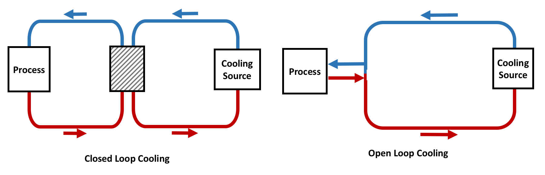
Por que os chillers de circuito fechado superam os sistemas abertos
Vantagem de estabilidade térmica
Os sistemas de circuito fechado têm flutuações térmicas significativamente mais baixas porque:
- Sem exposição ambiental direta: Fluido de processo isolado das condições ambientais
- Volume de fluido interno controlado: Massa térmica conhecida para resposta previsível
- Interface de troca de calor estável: Coeficientes de transferência de calor consistentes
- Controle preciso da qualidade da água: Resistividade à água DI >18 MΩ·cm mantida
| Parâmetro | Ciclo Fechado | Ciclo Aberto | Melhoria |
| Estabilidade de temperatura | ±0,05–0,2°C | ±0,5–2,0°C | 5–10× melhor |
| Tempo de resposta | 5–30 segundos | 30–120 segundos | 2–4× mais rápido |
| Controle de qualidade da água | Água DI, >18 MΩ·cm | Água da torre, variável | Ultra-puro |
| Risco de contaminação | Muito baixo | Alto (aerotransportado, biológico) | Significativo |
| Variação sazonal | Mínimo | Significativo | Desacoplado do ambiente |
Eficiência Energética em Carga Estável
Em fábricas de semicondutores, as cargas são relativamente estáveis em comparação com ambientes industriais, permitindo a otimização da eficiência em estado estacionário.
Métricas de Eficiência Energética:
COP (Coeficiente de Desempenho):
COP = Qresfriamento /Pentrada
IPLV (valor de carga parcial integrada):
IPLV = 0,01A + 0,42B + 0,45C + 0,12D
Onde A, B, C, D = COP em 100%, 75%, 50%, 25% de carga
Chiller semicondutor típico:
• COP: 4,0–6,0 (resfriado a água), 3,0–4,5 (resfriado a ar)
• IPLV: 5,0–7,0 (resfriado a água), 3,5–5,0 (resfriado a ar)
Os chillers de circuito fechado otimizam:
- Eficiência do ciclo do compressor: O VFD reduz as perdas de ciclagem em 20–40%
- Desempenho de carga parcial: IPLV normalmente 20–30% melhor que COP de carga total
- Potencial de recuperação de calor: 60–80% do trabalho do compressor recuperável para aquecimento de instalações
Complexidade de manutenção reduzida
Como o sistema é selado:
- Sem manutenção de torre de resfriamento: Elimina a limpeza da bacia, eliminação de deriva, substituição de enchimento
- Sem controle de contaminação da água: Sem risco de crescimento biológico, algas ou Legionella
- Risco de corrosão reduzido: Sistema fechado com química controlada da água
- Maior vida útil do sistema: Típico 15–20 anos versus 10–15 anos para sistemas abertos
- Custos mais baixos de tratamento de água: Consumo mínimo de produtos químicos
Isso é especialmente importante em fábricas de semicondutores 24 horas por dia, 7 dias por semana, onde as janelas de manutenção são limitadas.
Integração com equipamentos de processamento de wafer
Os chillers de circuito fechado são comumente integrados com:
| Tipo de equipamento | Requisitos de resfriamento | Configuração Típica | Padrão de interface |
|---|---|---|---|
| Sistemas de Litografia (DUV/EUV) | Óptica, retículo, palco wafer, iluminação | Multizona, ultraprecisão | SECS/GEM, OPC-UA |
| Ferramentas de gravação (RIE, ICP, DRIE) | ESC, paredes da câmara, gerador de RF | Resposta rápida e multi-loop | SEG/GEM |
| Deposição (CVD, PVD, ALD) | Câmara, chuveiro, aquecedor | Multizona, alta capacidade | SEG/GEM |
| Implantação Iônica | Linha de feixe, alvo, analisador | Multi-loop, precisão | SEG/GEM |
| Metrologia (CD-SEM, AFM) | Palco, óptica, eletrônica | Zona única/multizona | Varia |
| Processamento a Vácuo | Bombas, câmaras, medidores | Loop único, precisão moderada | Varia |
Cada sistema pode exigir zonas de controle térmico independentes, dependendo da sensibilidade do processo. Fábricas avançadas geralmente são implantadas arquiteturas de chillers multi-loop para suportar diferentes zonas de temperatura dentro da mesma linha de produção.
Arquitetura Térmica Multizona
| Zona | Carga térmica | Temperatura | Estabilidade | Fluido |
| Mandril Eletrostático (ESC) | 2–5 kW | -20 a +80°C | ±0,1°C | Água DI/glicol |
| Paredes da Câmara | 3–8 kW | 20–40°C | ±0,5°C | NA água |
| Gerador de RF | 1–3 kW | 20–30°C | ±1,0°C | NA água |
| Bomba de vácuo | 1–2 kW | 20–40°C | ±2,0°C | NA água |
| Total | 7–18 kW | - | - | - |
Redundância em sistemas de resfriamento de semicondutores
Na fabricação de semicondutores, o tempo de inatividade é extremamente caro. Uma única interrupção térmica pode resultar em:
- Perda de lote de wafer: $50.000–$500.000+ por lote dependendo do produto
- Instabilidade do processo: Horas a dias de requalificação
- Requisitos de recalibração da ferramenta: 4–24 horas de produção perdida
- Atrasos na produção: Efeitos cascata através de uma programação fabulosa
Opções de arquitetura de redundância
| Configuração | Descrição | Disponibilidade | Custo Premium | Inscrição |
| N+1 | Uma unidade de backup para N unidades operacionais | 99,5–99,9% | +15–25% | Produção padrão |
| 2N | Totalmente redundante (backup 100%) | 99,9–99,99% | +80–100% | Ferramentas críticas |
| 2N+1 | Totalmente redundante com sobressalente | 99,99%+ | +100–120% | Ultracrítico (EUV) |
| Loop duplo | Dois circuitos de resfriamento independentes por ferramenta | 99,9%+ | +50–70% | Ferramentas multizona |
Os sistemas de resfriamento de circuito fechado são frequentemente projetados com:
- Redundância N+1: Um chiller standby para cada N chillers em operação
- Sistemas de bomba dupla: Comutação automática em caso de falha da bomba
- Módulos compressores de backup: Cartuchos de compressor de troca rápida
- Loops de resfriamento paralelos: Loops independentes para zonas críticas
- UPS para sistemas de controle: Alimentação ininterrupta para controles e sensores
Sistemas de comutação automática
Os sistemas redundantes modernos incluem capacidade de comutação automática:
- Gatilho de desvio de temperatura: Comutação quando a temperatura excede ±0,2°C do ponto de ajuste
- Gatilho de desvio de fluxo: Comutação quando o fluxo cai abaixo de 90% do ponto de ajuste
- Gatilho de falha do equipamento: Comutação no compressor, bomba ou falha no sensor
- Tempo de transição: <30 segundos para manter a continuidade do processo
Conclusão
Os chillers de circuito fechado desempenham um papel fundamental nos modernos equipamentos de processamento de wafer, fornecendo controle de temperatura ultraestável, livre de contaminação e altamente preciso.
Principais vantagens técnicas de sistemas de circuito fechado para fabricação de semicondutores:
- Estabilidade térmica: ±0,05–0,2°C alcançável, 5–10× melhor que sistemas abertos
- Controle de contaminação: Qualidade da água DI >18 MΩ·cm mantida em todo o sistema
- Repetibilidade do processo: Condições térmicas consistentes permitem fabricação de alto rendimento
- Eficiência energética: COP de 4,0–6,0 com compressores VFD e controle otimizado
- Confiabilidade: Vida útil do sistema de 15 a 20 anos com manutenção adequada
Considerações críticas de design para resfriadores semicondutores:
- Seleção de compressor: Scroll ou parafuso acionado por inversor para estabilidade de modulação
- Projeto do evaporador: Placa soldada para alta eficiência e baixa carga de refrigerante
- Sistema de controle: PID com ajuste adaptativo, feedforward e recursos preditivos
- Redundância: Configuração N+1 ou 2N para aplicações críticas
- Integração: Interface SECS/GEM para automação fabril
À medida que a tecnologia de semicondutores continua a avançar em direção a nós menores (<5 nm) e novas arquiteturas (GAA, chips), os sistemas de resfriamento de circuito fechado se tornarão ainda mais críticos no suporte à fabricação de wafers de próxima geração. Os requisitos de precisão térmica serão cada vez mais rigorosos ±0,01°C ou melhor, para processos críticos, exigindo inovação contínua em:
- Algoritmos de controle de temperatura de ultraprecisão
- Projetos de sistemas de baixa inércia térmica
- Gerenciamento térmico independente de múltiplas zonas
- Controle térmico preditivo baseado em IA
- Tecnologias sustentáveis de refrigerantes e energia
Em última análise, a precisão térmica determina diretamente o rendimento, o desempenho do dispositivo e o sucesso da fabricação na fabricação avançada de semicondutores.