
How refrigeration compressors work
1.HERMETIC Refrigeration compressor or (fridge compressor)
Hermetic compressors are mostly used in household refrigerators, both motor and compressor are enclosed in a steel housing also known as a hermetic container where no gas or liquid can enter or escape from the welding seals welded around the container.
The hermetic compressor has a direct drive with no coupling and no mechanical seal.
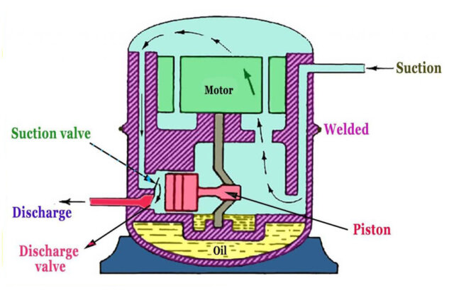
The hermetic compressor has a low-pressure housing, which means that the interior of the compressor housing is subjected only to suction pressure whereas discharge can cause stress hazard inside the compressor.
The refrigerant and compressor oil inside the compressor housing is totally in contact with the motor rotor and stator windings. So, to avoid any short circuit within the motor winding the refrigerant used must have a high dielectric strength and must be fully compatible with the insulation material.
The electric motor is directly connected to the compressor with a single shaft avoiding the use of any coupling or mechanical seal and leaving no chance of refrigerant leaking into the atmosphere.
The crankshaft is designed to circulate lubricating oil from the pump to all bearing surfaces.
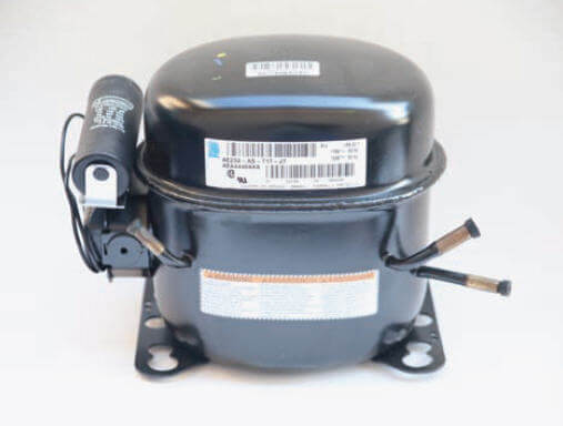
A typical household hermetic compressor may be used continuously for more than 20 years, but often at the end of its service period, it is moved to secondary duty like it can be used as a refrigerant evacuation pump after some modification, traded and resold, or discarded.
Since the motor, as well as the compressor, is not accessible for repair or maintenance, a failure of the inbuilt motor winding like short circuit can cause decomposition of the refrigerant and serious contamination to the crankcase lubricating oil.
Therefore to avoid such damage, internal and external motor protection devices shuts off the motor power supply in case of any fault.
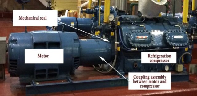
2. Commercial Refrigeration Compressor
The compressor is usually a reciprocating or a screw compressor. It provides the differential pressure and a necessary flow around the system by raising the refrigerant temperature and pressure thereby giving a desired mass flow rate.
The purpose of the compressor in the refrigeration cycle is to accept the low-pressure dry gas from the evaporator and raise its pressure to that of the condenser.
The rate of heat absorption by the evaporator differs from different cargoes carried and the outside air temperature.
Sometimes cargo/stores are freshly located in a warm climate, the cooling load on the system increases significantly.
Therefore, most large compressors are multi-unit v –type compressor fitted with some arrangement of load or capacity control.
The load controller senses the temperature and controls the capacity of the compressor by off-loading or cutting out one of the compressor unit.
For the reciprocating units, this is carried out by using unloader push pins to keep the suction valve lifted from their seats.
2a. Question: Why a coupling is needed in a commercial refrigeration compressor and motor?
Couplings are used to connect large compressor shaft with the compressor motor shaft, a driving force in these large units are very high.
- The coupling can allow some amount of flexibility during miss alignment of shafts.
- It can save the compressor when there is a sudden excess torque by allowing limited slip or twist.
2b. Question: What is the function of a Mechanical Seal in a refrigeration compressor?
The mechanical seal screwed on the rotating compressor shaft provides sealing of crankcase, also contains the crankcase pressure and prevents any contamination from outside substance.
3. Thermostatic expansion valve (TEV or TXV)| Metering valve?
Thermostatic expansion valve acts as a regulator where the refrigerant is metered from the high-pressure side to the low-pressure side of the system.
- Expansion valve controls the flow of refrigerant to the evaporator according to the load.
- Expansion valve prevents the liquid refrigerant from entering into the compressor.
- It maintains 6°C to 7°C of superheat at the outlet of the evaporator.
- Expansion valve helps to maintain an appropriate amount of refrigerant in the high-pressure side and low-pressure side of the system.
4. Why an equalizing line required in thermostatic expansion valve (TEV) or metering valve?
There is always pressure drop across the evaporator in practical, and it’s even higher in large evaporators.
Thus evaporator having a pressure drop of 0.15 kg/cm2 and above should have an equalizing line attached at the evaporator outlet. Otherwise, the evaporator gets starved of refrigerant.
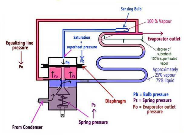
In an expansion valve, the pressure acting on the top of the diaphragm (Pb) corresponds to saturation pressure plus a degree of superheat of the refrigerant leaving the evaporator.
Thus the pressure (Pb) is trying to open the valve against the spring force (Ps) from below the diaphragm.
The equalizing line has a saturation pressure (Po) of the refrigerant leaving the evaporator to act below the diaphragm.
Thus both the saturation pressures of Pb and Po cancel out each other, therefore the degree of superheat of (Pb) is supposed to open the expansion valve to maintain 6° to 7° of superheat and ensuring no liquid enters the compressor suction.
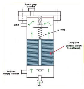
5. FILTER-DRIER in a refrigeration system
A filter drier installed in the liquid line at the condenser coil outlet to filter or trap minute foreign particles and absorb any moisture or water present in the system.
Moisture may cause failure of compressor valves in case of hermetic compressor often causes breakdown of the motor winding insulation resulting in short-circuiting or grounding of the motor.
Presence of moisture may deteriorate the property of lubricating oil and may cause the formation of metallic or other acidic sludge which may lead to clogging or chocking of valves and other oil passages.
Moisture reacts with the refrigerant to form an acidic solution. This acidic solution dissolves copper tubings and extracts copper from copper-based alloys like brass or bronze present in different parts of an air conditioning system.
This copper gets deposited into the compressor bearings and valves as a “copper plating” which may lead to system leaks, improper evacuation or vacuum of the system, malfunction of filter/drier, contamination of the oil and the refrigerant.
The desiccant absorbs the moisture; desiccant material can be solid or liquid.
The solid desiccant is silica gel, activated alumina, zeolites, titanium dioxide whereas the commercial solid desiccant is activated carbons, metal oxides and specially developed porous metal hydrides.
Silica gel is one of the best performing and commonly used materials in desiccant having its good long-term stability.
However, it is not a heat-resistant material and therefore is only adequate for low-temperature systems only.
Today’s common driers are capsule charged with a solid desiccant such as activated alumina or zeolite with acid absorbing capabilities and protect the valve orifice of the thermostatic expansion valve from damage by fine debris.
Nowadays driers are compatible with all the commercially available refrigerants including r-410a.
Large driers made in such a manner that it can be opened to remove the used moisture absorbing agent and replace it with a new one whereas small size driers get’s replaced as a full unit.
Suction line filter-driers are a temporary installation to clean up the system, after service, we must discard if the pressure drops below the set pressure.
Chocked drier can starve the evaporator of refrigerant and may lead to a longer running time of compressor.
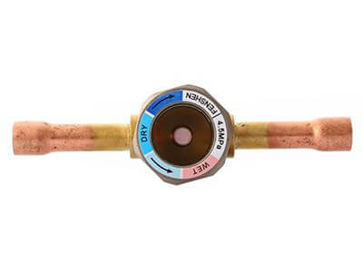
6. Sight glass|Moisture indicator
Sight glass gives a more accurate reading in a horizontal position and shows up bubbles on the top of sight glass/moisture indicator.
In the vertical position, the refrigerant gas bubbles goes anywhere in the sight glass/moisture indicator.
Presence of bubbles in sight glass during normal operation indicates low refrigerant.
Sight glasses are used to indicate whether refrigerant vapors are present in the pipe, which should be carrying only liquid refrigerant.
The sight glass is installed closest to the thermostatic expansion valve so as to determine how much liquid is present at the expansion valve and being drawn from the filter drier; it can also be used to indicate the moisture content present in the refrigerant.
An indication of only liquid means the system is correctly working while the presence of any gas bubbles means the system is getting short of refrigerant.
Moisture indicating sight glasses have a colour indicator which changes colour when the moisture content of the refrigerant exceeds the critical value
Commonly used materials for sight glass are brass metals and for ammonia, it’s steel or cast iron.
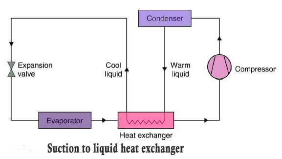
7. Heat exchangers in a Refrigeration system
Cold refrigerant leaving the evaporator coil outlet can be used to under cool the warm liquid refrigerant leaving from the condenser outlet by using a heat exchanger as shown in the diagram known as suction to the liquid heat exchanger.
By cooling and removing the enthalpy (heat) from the warm liquid refrigerant and then releasing to the inlet of the expansion valve provides more efficient use of the evaporator surface.
Greater refrigeration effect and reduction in the refrigerant mass flow into the compressor.
The drawback of this system can be the evaporator unable to provide required superheat to the refrigerant entering at the suction of the compressor.
A mix of vapor and liquid refrigerant entering into compressor suction may cause severe damage to the compressor.
Therefore the overall effect of fitting such a heat exchanger varies with the refrigerants thermodynamic property and its operating conditions.
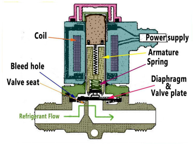
8. Solenoid Valve
The solenoid valve is an electromagnetic valve for automatic opening and closing of liquid and gas lines.
When the coil gets energized, the diaphragm valve plate moves up into the open position and vice versa when the coil is de-energized.
The bleed hole allows the refrigerant to pressurize the top side of the diaphragm to provide a tight seating closure when the solenoid valve is in a closed position.
Solenoid valves are used in refrigeration and air-conditioning systems (HVAC) to isolate the thermostatic expansion valve to avoid evaporator flooding.
A burnt-out coil, a damaged diaphragm, or blockage by dirt, causes the solenoid valve to malfunction.
9. Back Pressure Valve
Back pressure valve may sometimes be fitted into the system to hold back a high evaporator pressure, where two to three evaporator outlet feeds into a common compressor suction line.
Back pressure valve is fitted at the outlet of the evaporator in a multi-temperature zone system as shown in the diagram.
Back pressure valves are usually fitted at warmer rooms where the temperature is set at 4°C to 5°C or higher for eg. Vegetable storeroom or lobby.
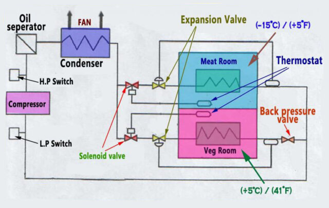
If there is no back pressure valve, then it can lead to low temperatures or over flooding of the evaporator which could cause a problem like freezing in water coolers and spoilage of perishable items like vegetables and fruits.
It creates back pressure on the evaporator coil and ensures that most of the liquid refrigerant is made available at lower temperature zones like meat or fish room.
Back pressure valves are spring loaded and a non-return valve.
10. Compressor Safety Devices:
a. Refrigeration Compressor Unloader Safety device
Large refrigerating compressors are running with 2 to 3 units in a v or w type arrangement, provided with an unloading mechanism.
It enables the compressor to start easily with no vapor pressure load in the cylinder unit thereby permitting the use of electric motors with low starting torques.
Unloading mechanism works by raising the suction valve at the open position so that the gas moves freely in and out through the valve without compression.
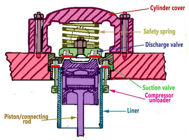
Unloader mechanism works by the release of oil pressure from compressor crankcase oil pump via a solenoid valve to the compressor unloader. The solenoid valve gets its signal from the load control system.
The discharge valve body is held in place by a safety spring as shown in the image which is fitted to allow the complete discharge valve to lift in the event of liquid carry over to the compressor.
The unloader system is used for capacity control by successively cutting in or out cylinders or cylinder groups.
Other methods of capacity control include varying the compressor speed, and ‘hot gas bypass, which involves passing a proportion of the discharge gas from the compressor directly to the evaporator and bypassing the condenser.
b. Compressor High Pressure cut out Safety Device
The compressor fitted with discharge high-pressure trip prevents over-pressurization of the system and overload of the compressor motor.
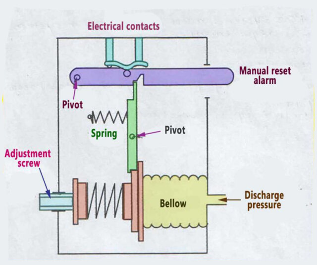
Some high-pressure switch controls the restart of the compressor automatically on a drop in pressure; others have a manual reset mechanism.
The high-pressure cutout switch stops the compressor motor at a pressure of about 90% of the maximum working pressure of the system.
c. Compressor Low Pressure cut out Safety Device
Low-pressure cutout switch is used to protect against too low suction pressure, which usually indicates a blockage by dirt, ice formation if water is present in the system or loss of refrigerant.
The control is normally set to stop the compressor at a pressure corresponding to a saturation temperature of 5°C or 41°F below the lowest evaporating temperature.
In some small plants, it is also used as a temperature controller ie. stopping and starting of the compressor to maintain the desired pressure and temperature.
d. Compressor Differential Lube oil pressure Safety Device
Differential lube oil pressure switch is used to protect against, too low oil pressure in forced lubrication systems. It is a differential control, using two bellows. One side responds to the low side suction pressure and the other response to the oil pressure.
The oil pressure must be greater than suction pressure for the oil to flow out of the bearings. If the oil pressure fails or falls below a minimum value, differential lube oil pressure switch stops the compressor after a few seconds has elapsed.
The refrigerating compressor crankcase has refrigerant under suction pressure.
The lube oil pressure needs to be more than the suction pressure for the lube oil to come out of the bearings.
Lube oil pressure must be greater than the crankcase suction pressure else the bearings may get damaged due to the loss of lubrication.
Lub oil pressure is set at 2 bar above the suction pressure.
11. How to remove oil from Refrigeration System?
Some oil always gets carried over with the compressed refrigerant gas and must be removed.
Oil Separator function:
- To prevent oil from entering and fouling the internal surfaces of the evaporator and other heat exchangers its important that the oil return in refrigeration compressor.
- To ensure oil gets a return to the compressor crankcase, preventing any failure of moving mechanical parts from any shortage of oil.
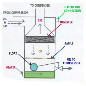
Oil separator fitted between the compressor and condenser with internal baffles and screens to remove oil from oil/refrigerant mixture.
The separation of oil is mechanical by slowing down and changing the direction of the gas/oil stream mixture.
The oil separated from the refrigerant gets collected in the bottom of the separator and again returned to the crankcase or receiver through an automatic float valve.
12. Why refrigeration compressor takes suction from its crankcase?
The outlet of the evaporator coil leads into to the compressor crankcase, and the advantages of this design are:
- Since crankcase is pressurized, no air can enter into the system.
- Helps in the lubrication of compressor piston, liner, and other moving metal parts.
- Refrigerant gas is miscible with oil; this property helps the gas to bring the oil back into the system via the Oil Separator.
13. Thermostats
Thermostats are temperature-controlled electric switches, used for both safety and control functions. When fitted to compressor discharge lines, they are set to stop the compressor if the discharge temperature is too high.
Thermostats are also used to control the temperature in a refrigerated space by cycling the compressor ‘on and off ’ and by ‘opening and closing’ a solenoid valve in the liquid line.
Three types of elements are used to sense and relay temperature changes to the electrical contacts.
- A fluid-filled bulb connected through a capillary to a bellows.
- A thermistor.
- A bi-metal element.
The above controls are set by the plant’s instruction manual and should be checked regularly for refrigerant leaks from the bellows and connecting tubes. The electrical contacts should be examined for signs of wear and arcing.
14. Pressure Relief Safety Device
Refrigeration systems are designed to withstand a maximum working pressure (MWP) which, if exceeded as a result of a fire, extreme temperature conditions, or faulty electrical controls, may cause some part of the system to explode.
To avoid an explosion or sudden rise in pressure compressors and pressure vessels are fitted with a pressure relief device.
There are three types of relief devices
- Spring-loaded relief valves remain set to open at the MWP and close when the pressure drops to a safe level. Relief valves must not be interfered while in service and must be locked or sealed to prevent unauthorized adjustment.
- Bursting discs, which comprise thin metal diaphragms designed to burst at a pressure equal to the MWP.
- Fusible plugs, which contain a metal alloy, melts when the temperature in the system corresponding to the MWP.
Commonly the discharge from relief device vented directly into the atmosphere.
In some plants, relief devices are arranged to discharge toward the low-pressure side of the system.
15. Refrigeration system: Hot gas Bypass valve
Hot gas bypass valves used in compressors do not have a capacity reduction device like compressor unloader.
Bypass valve regulates the cooling capacity by injecting discharge gas back into the suction.
It keeps the evaporator pressure constant regardless of the load. It is a constant pressure valve, balancing between the suction pressure against the pre-set spring force.
I’m so thankful to read this helpful topic about refrigeration
Good knowledge 👌 thanks for your kind support
Buenos días,
Me podría decir el funcionamiento
Del sensor de capacidad de un compresor
De tornillo