
Why do we need to vacuum a chiller system?
All the refrigeration systems are designed to run without moisture and non-condensable gases; else it may not work as designed and is likely to fail prematurely.
The presence of moisture in the air conditioning system may lead to the formation of acidic sludge. It may cause restrictions on various places like expansion valves, evaporator coils, reducing the overall cooling effect.
In case of a hermetic compressor, it may cause deterioration of the insulation winding, leading to a short circuit and compressor motor burnout.
Non-condensable gases are just air that can enter during refrigerant charging, repair, or maintenance. These gases take up space in the condenser and limit the amount of liquid refrigerant leading to reduced cooling efficiency.
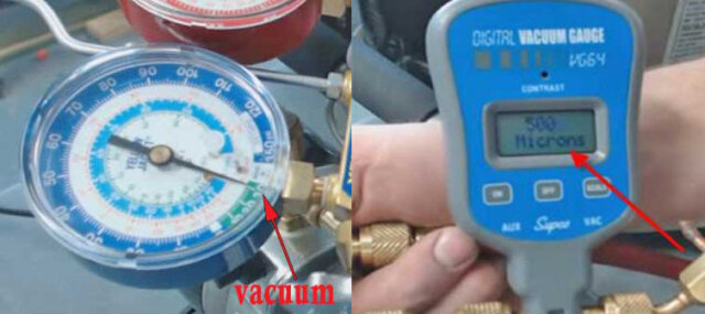
Evacuation is carried out by using a vacuum pump and a recovery bottle, ones the system evacuates. We need to wait for about 20-25 min to check the pressure gauge is holding the negative pressure (vacuum) as shown in the image.
This process may ensure that there are no leakages in the system as chances of air or moisture could enter via pipe cracks or leaky gaskets or joints while performing evacuation procedures.
In the above image, we can see two devices fitted one is an analog pressure gauge showing the final negative reading, and another one is a digital vacuum gauge showing 500 microns as final reading, connected to the same line to ensure the system is 100% evacuated.
Liquid refrigerant charging
Liquid refrigerants are normally added to the liquid line following proper conditions. If any heating method is used to inject vapour refrigerant into the suction line, 100% vapour must enter the compressor.
Liquid refrigerant is incompressible and can cause severe damage to any compressor.
Refrigerant Gas charging
Always charge the vapor refrigerant from the point where the system pressure is lower than the pressure in the charging cylinder.
If we try to charge from the discharge side of the compressor, then instead of refrigerant going from the charging cylinder to the system, it may start reversing, filling the charging cylinder itself.
Remember that high pressure flows towards the lower side.
Only during refrigeration system evacuation or when the system is insufficient of refrigerant, the refrigerant can be inserted into both the high and low-pressure sides of the HVAC unit.
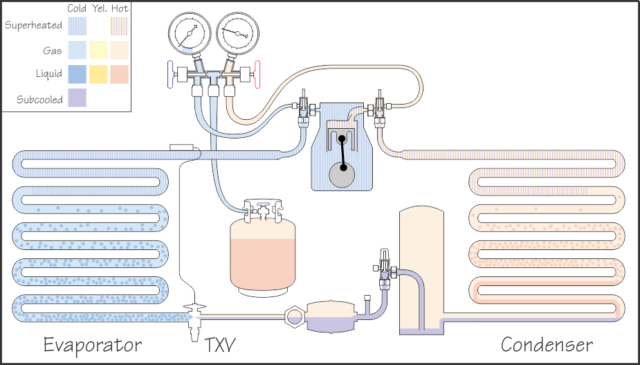
Mostly large charging cylinder has two valves. The red one is connected to the dip tube and is for liquid charging. The Blue one is connected from the top with no dip tube and is for gas charging. In both, the conditions cylinder is kept in an upright position while charging.
If the refrigerant charging cylinder has only one valve, then we don’t have a dip tube, and in this case, It’s necessary to invert the cylinder for liquid charging.
What is Copper Plating process in a refrigerating system?
When moisture is present in the system, it combines with the refrigerant to form an acidic solution.
This acidic solution dissolves copper tubings and extracts copper from copper-based alloys like brass or bronze present in different parts of an air conditioning system, mainly pipings.
This copper gets deposited into the compressor bearings and suction/discharge valves as a copper plating which may lead to refrigerant system leaks, long-running refrigeration plant, drop in the overall cooling efficiency of the refrigeration system, chocking of filter/drier, contamination of refrigerant, and oil.
Continuing with our vapor charging process, the charging cylinder can be weighed before charging by using a weighing scale.
Case: Refrigerant gas charging in ac | air conditioner
Considering that we have are very low in refrigerant and need to replenish whole of the system with a fresh charge.
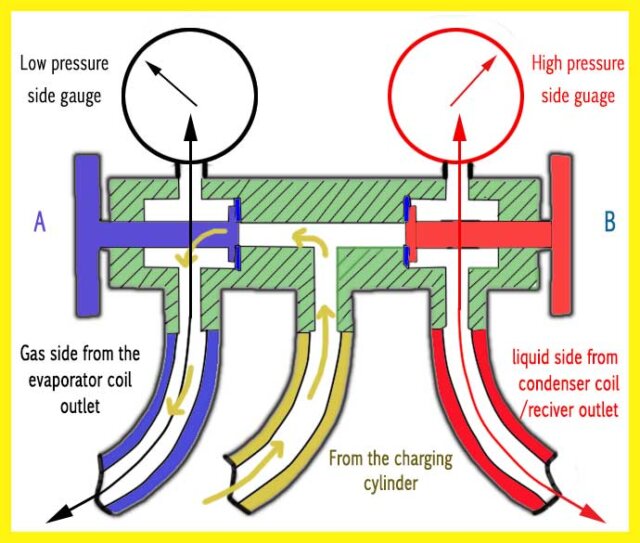
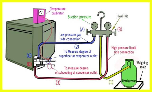
- Connect hose 2 and 3 connection to C and D, respectively.
- Both the gauges must be zeroed.
- Attach the temperature probe at the correct location near the sensing bulb to sense the degree of superheat.

- Evacuate the system into a recovery bottle by connecting the vacuum pump to charging hose 1, open both valves A and valve B till the evacuation process is complete (vacuum gauge reading showing 500 microns as final reading).
- Stop the vacuum pump after the system has evacuated, close the charging hose (1) valve going to the recovery bottle, check the pressure drop in the gauge for around 20 min to know if there is any leakage in the system.
- Disconnect the charging hose 1 from the vacuum pump and connect it to the blue connection of the charging cylinder for a gas charge.
- Open valve A, slightly open the connection at C and purge the whole hose line from 1 to 2 by crack opening the gas valve of the refrigerant charging bottle; try not to avoid any excess leak directly into the environment.
- Same way, purge the high-pressure liquid side hoses from 1 to 3 to remove any air/moisture inside the hose.
- Now tight both the low and high-pressure side hose at position C & D, respectively as shown in the image.
- Start charging the gas refrigerant from the refrigerant bottle to the low-pressure side of the system at connection C by opening valve A and the refrigerant valve of the charging bottle until the vacuum comes to zero.
- Now start the compressor as the suction pressure goes above zero.
- After about 30 – 40 seconds of charging, close valve A and check the suction gauge pressure for a rise in pressure.
- Keep monitoring the degree of superheat by the temperature calibrator to ensure the liquid is not entering into compressor suction also; we can calculate how much charge present in the system by the pressure chart.
- If the superheat temperature is high, then it means the system is running low in refrigerant, whereas a lower superheat temperature than the desired reading means the system is overcharged.
- Repeat the procedure 10 to 11 until the suction pressure reaches 60 psi (as per maker). This avoids the risk of overcharging of the system also keeps measuring the refrigerant by the weighing scale.
- Once the refrigerant has charged, close the refrigerant valve, valve A and B and disconnect all the hoses, and secure everything.
Amazing, A lesson to all hvac technician thank.
Great efforts by SCY to produce such guidence to all HVACR Tech.
Thankyou.
Thank you so much for your service
Buen dia como hago para octener su manual de especificacionaes osea toda esta instruccion que usted da aca gracias mi correo es [email protected]
Hola. Hola, mi nombre es Marcelo, y soy un estudiante, de Argentina. Gracias por la información detallada.
You are welcome, Marcelo
Muy bueno éste espacio, gracias por compartir tus conocimientos
دغدغه من پیداکردن کلاس خصوصی و معلم خصوصی خوب بود که به کمک این مقاله دغدغه ام برطرف شد