
Bei der Leiterplattenherstellung wirkt sich die Temperaturkontrolle direkt auf die Produktqualität, die Prozessstabilität und die Produktionseffizienz aus. Im Gegensatz zu allgemeinen industriellen Kühlanwendungen umfasst die Leiterplattenproduktion mehrere gleichzeitig ablaufende wärmeempfindliche Prozesse, darunter CNC-Bohren, Galvanisieren, Ätzen, Laminieren, Belichten und AOI-Inspektion. Jeder Prozess hat unterschiedliche thermische Eigenschaften, Lastschwankungen und Temperaturstabilitätsanforderungen.
Die Herausforderung des Wärmemanagements bei der Leiterplattenherstellung ist gekennzeichnet durch: Mehrpunkt-Thermokopplung, wo benachbarte Prozessanlagen die thermische Umgebung gegenseitig beeinflussen können. Diese räumliche thermische Wechselwirkung erfordert ein sorgfältiges Design auf Systemebene und keine isolierten Kühllösungen auf Geräteebene.
Aus diesem Grund sind Leiterplattenkühlsysteme nicht nur darauf ausgelegt, Wärme abzuleiten. Ihr eigentlicher Zweck besteht darin, während des gesamten Produktionsprozesses ein stabiles thermisches Umfeld aufrechtzuerhalten und so beides auszugleichen stationäre thermische Belastungen Und vorübergehende thermische Störungen.
Bei der modernen Leiterplatten- und HDI-Herstellung mit hoher Dichte können selbst kleine Temperaturschwankungen zu Maßabweichungen (typischerweise ±0,02 mm Toleranz für HDI-Platinen), ungleichmäßiger Kupferabscheidung, Problemen mit der Signalintegrität oder Fehlern bei der Ausrichtung mehrerer Schichten führen. Da die Leiterplattendichte und die Signalfrequenz weiter zunehmen, werden Kühlsysteme zu einem Teil der Prozesstechnik selbst und nicht mehr zu Hilfsanlagen in der Fabrik.
Thermische Eigenschaften von Leiterplattenherstellungsprozessen
In den verschiedenen Phasen der Leiterplattenproduktion entsteht Wärme auf unterschiedliche Weise. Das Verständnis dieser thermischen Verhaltensweisen – einschließlich Wärmeerzeugungsmechanismen, thermischer Zeitkonstanten und zulässiger Temperaturbänder – ist die Grundlage für die Auswahl der richtigen Kühllösung.
| PCB-Prozess | Hauptwärmequelle | Kühlziel | Typische Wärmebelastung | Temperaturempfindlichkeit | Zulässige Variation |
|---|---|---|---|---|---|
| CNC-Bohren | Spindelreibung, Bit-Substrat-Schnittstelle | Reduzieren Sie die Wärmeausdehnung | 1,5–4,0 kW pro Spindel | Sehr hoch | ±0,5°C |
| Galvanisieren | Faradayscher Widerstand, Joulesche Erwärmung | Stabilisierung der Beschichtungsdicke | 8–25 kW pro Tank (je nach Tankgröße) | Extrem hoch | ±0,2–0,5 °C |
| Radierung | Exotherme chemische Reaktionen, Sprühstoß | Behalten Sie die Reaktionskonsistenz bei | 3–12 kW pro Leitungsabschnitt | Hoch | ±1,0°C |
| Laminierung | Pressplatten, exotherme Aushärtung | Verhindern Sie Plattenverzug und kontrollieren Sie das Aushärtungsprofil | 15–50 kW pro Presse | Hoch | ±2,0°C (Zonengleichmäßigkeit) |
| Laserbohren (CO₂/UV) | Abwärme der Laserquelle, abgetragenes Material | Optik schützen, Neuverguss des Harzes verhindern | 2–8 kW pro Lasereinheit | Sehr hoch | ±0,3°C |
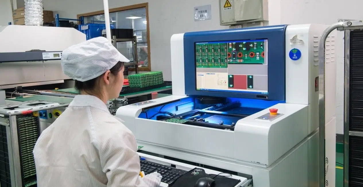
| AOI / Inspektion | Beleuchtungssysteme, Kameras, Prozessoren | Sorgen Sie für die Stabilität des optischen Pfades | 00,5–2,0 kW pro System | Mittel | ±2,0°C |
Thermische Dynamik beim mechanischen Bohren
Bei mechanischen Bohrprozessen überschreiten die Spindelgeschwindigkeiten häufig 100.000 U/min (typischerweise 120.000–200.000 U/min beim Mikrobohren). Durch die Reibung zwischen Bohrern und PCB-Substraten entsteht örtlich begrenzte Wärme an der Schnittstelle zwischen Bohrer und Bohrer. Die Wärmestromdichte kann erreichen 10–50 W/mm² bei aggressiven Bohrzyklen.
Dieser lokalisierte Wärmeeintrag verursacht zwei Hauptprobleme:
- Thermomechanischer Stress: Die unterschiedliche Wärmeausdehnung zwischen dem Bohrer (typischerweise Wolframcarbid mit α ≈ 4,9×10⁻⁶/°C) und dem PCB-Substrat (FR-4 mit α ≈ 12–18×10⁻⁶/°C) führt zu Mikrobrüchen an der Lochwand.
- Harzverschmierung**: Erhöhte Temperaturen (normalerweise > 150 °C an der Bohrerspitze) erweichen das Epoxidharz und fließen zurück, wodurch es über den Zylinder und die Wand des Lochs verschmiert und die Integrität der Zylinderwand beeinträchtigt.
Besonders kritisch wird dies bei HDI-Platinen, bei denen es typischerweise zu Mikrovia-Toleranzen kommt ±0,020 mm (20 μm), was eine Temperaturstabilität unter 0,5 °C in der Bohrzone erfordert.
Thermische Elektrochemie beim Plattieren und Ätzen
In Galvanik- und Ätzlinien ist das thermische Verhalten eher chemisch bedingt. Die Temperatur hat direkten Einfluss auf:
- Austauschstromdichte: Gemäß der Butler-Volmer-Gleichung hängt die Reaktionskinetik exponentiell von der Temperatur ab (typischerweise 2–3 % pro °C-Anstieg bei der Kupferabscheidung).
- Elektrolytleitfähigkeit: Die Ionenleitfähigkeit steigt um etwa 2 % pro °C-Anstieg
- Diffusionskoeffizient: Die Massentransportraten nehmen mit der Temperatur zu, was sich auf Streuvermögen und Gleichmäßigkeit auswirkt
Zu hohe Temperaturen können die Reaktionsgeschwindigkeit vorübergehend verbessern, verringern jedoch häufig die Konsistenz der Beschichtung und die Prozessstabilität. Für die saure Verkupferung liegt der optimale Temperaturbereich typischerweise bei 22–28°C, mit einer Empfindlichkeit der Abscheidungsrate von ca ±0,05 μm/min pro °C Abweichung.
Thermomechanische Herausforderungen bei der Laminierung
Die Laminierung bringt eine weitere Art thermischer Herausforderung mit sich Glasübergangstemperatur (Tg) des Laminatmaterials. Während des Pressens:
- Das Laminat wird über seine Tg erhitzt (typischerweise 130–180 °C für Materialien mit hoher Tg).
- Der Harzfluss und die Aushärtung im B-Stadium erfolgen innerhalb eines engen Temperaturfensters
- Eine ungleichmäßige Abkühlung nach dem Pressen führt zu Wärmegradienten durch die gesamte Dicke
Es kann zu thermischer Restspannung durch ungleichmäßige Kühlung (normalerweise 5–15 °C Temperaturunterschied über das Panel) kommen Biege- und Verdrehungswerte über 0,5 %Dies führt zu nachgelagerten Registrierungsproblemen bei Bohr- und Bildgebungsprozessen.
Thermodynamik von Kühlsystemen mit geschlossenem Kreislauf
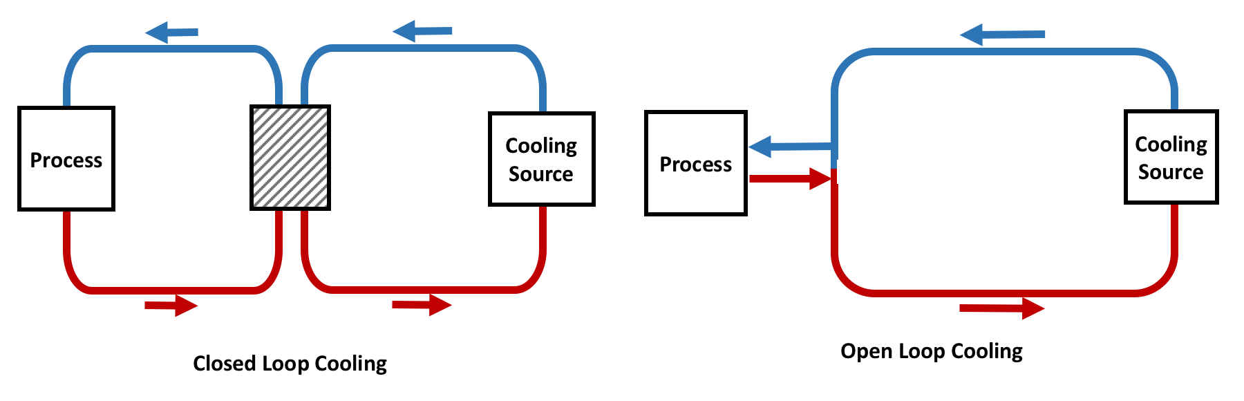
Die meisten modernen Leiterplattenfabriken verwenden Industriekühler mit geschlossenem Kreislauf, da diese eine stabile und isolierte Temperaturkontrolle ermöglichen. Für die ordnungsgemäße Systemspezifikation ist das Verständnis des Dampfkompressionskältekreislaufs von entscheidender Bedeutung.
COP = Qverdunsten / Wkomp = h1 - H4 / H2 - H1Bei typischen PCB-Kühlern liegt der COP je nach Betriebsbedingungen zwischen 3,0 und 6,5.
Analyse des Dampfkompressionszyklus
In einem standardmäßigen Dampfkompressionskühlkreislauf, der in PCB-Kühlern verwendet wird:
- Komprimierung (1→2): Kältemitteldampf mit niedrigem Druck wird auf hohen Druck komprimiert. Bei R-410A-Systemen erhöht sich dadurch typischerweise der Druck von ca. 9 bar (gesättigter Dampf bei 0 °C) auf ca. 26 bar (gesättigter Dampf bei 45 °C).
- Kondensation (2→3): Dampf mit hohem Druck und hoher Temperatur setzt Wärme frei und kondensiert. Die normalerweise aufrechterhaltene Unterkühlung beträgt 3–8 °C, um sicherzustellen, dass kein Dampf in das Expansionsgerät gelangt.
- Erweiterung (3→4): Flüssiges Kältemittel strömt durch eine Drosselvorrichtung (thermostatisches Expansionsventil oder elektronisches Expansionsventil) und fällt auf niedrigen Druck.
- Verdunstung (4→1): Eine Niederdruck-Flüssigkeits-Dampf-Mischung nimmt Wärme aus dem Prozesswasser auf und verdampft zu gesättigtem Dampf.
| Kältemittel | GWP | Typischer Betriebsdruck (bar) | Volumetrische Kühlleistung |
| R-410a | 2088 | 9–26 (Verdampfung/Verflüssigung) | Hoch (bevorzugt für mittelgroße bis große Systeme) |
| R-134a | 1430 | 3–12 | Moderat (kleinere Systeme) |
| R-513A | 573 | 4–14 | Moderat (Alternative mit niedrigerem GWP) |
| R-1234ze | 1 | 4–13 | Niedriger (zukünftige Option mit niedrigem GWP) |
Vorteile des Closed-Loop-Systems
In einem geschlossenen System:
- Das Prozesswasser zirkuliert unabhängig von der Außenumgebung und verhindert so eine Kontamination durch in der Luft befindliche Partikel und Mikroorganismen
- Der Wärmeaustausch erfolgt über Plattenwärmetauscher mit typischer Wirksamkeit von 85–95 %
- Das Risiko einer Wasserverschmutzung wird durch Filterung und Wasseraufbereitung verringert
- Aufgrund des konstanten Wassermassenflusses und bekannter thermischer Eigenschaften wird die Temperaturkontrolle vorhersehbarer
- Das geschlossene Kreislaufdesign ermöglicht eine präzise Wasserqualitätskontrolle (für Präzisionsanwendungen wird normalerweise ein spezifischer Widerstand von >1 MΩ·cm beibehalten).
Im Vergleich zu offenen Kühlsystemen bieten geschlossene Kühlsysteme Folgendes:
- Bessere Temperaturstabilität (typischerweise ±0,1–0,5 °C gegenüber ±1,0–3,0 °C für offene Systeme)
- Geringere Wartungshäufigkeit (keine Ablagerungen am Treibturm und kein Algenwachstum)
- Reduzierte Ablagerungen und Verunreinigungen in Prozesswärmetauschern
- Längere Gerätelebensdauer durch kontrollierte Wasserchemie
Kernkomponenten eines PCB-Kühlsystems
Kompressor: Dynamische Kühlleistungsregelung
Der Kompressor ist die primäre Energiequelle des Kühlsystems und verbraucht typischerweise Energie 25–40 % der gesamten Kältemaschinenleistung.

| Kompressortyp | Kapazitätsbereich | Teillasteffizienz | Geräuschpegel | Beste Anwendung |
| Scrollen (feste Geschwindigkeit) | 5–50 kW | Schlecht bei <50 % Auslastung | Niedrig | Konstante Belastung, kleine Systeme |
| Scroll (Wechselrichter) | 5–70 kW | Hervorragend (20–100 % Kapazität) | Mäßig | Unterschiedliche Lasten, die meisten PCB-Kühler |
| Schraube (feste Geschwindigkeit) | 50–300 kW | Mäßig | Hoch | Große Konstantlastsysteme |
| Schraube (Wechselrichter/VFD) | 50–500 kW | Exzellent | Hoch | Große Systeme mit variabler Last |
| Zentrifugal | >300 kW | Gut | Mäßig | Sehr große zentrale Pflanzen |
In modernen Leiterplattenanwendungen werden häufig Wechselrichterkompressoren (mit variabler Frequenz) verwendet, da sich die Produktionslasten ständig ändern. Maschinen starten und stoppen häufig, die Beladung der chemischen Bäder schwankt und Bohrsysteme arbeiten intermittierend mit Arbeitszyklen, die typischerweise zwischen 30–80 %.
Kompressoren mit variabler Frequenz ermöglichen dem Kühlsystem:
- Temperaturüberschreitung reduzieren (normalerweise). 0.5°C vs. 2–3°C für Ein/Aus-Steuerung)
- Verbessern Sie die Energieeffizienz (normalerweise 20–35 % Energieeinsparung bei Teillastbedingungen)
- Sorgen Sie für eine stabile Auslasswassertemperatur (normalerweise). ±0,1–0,3 °C Stabilität)
- Geringere zyklische Belastung des Kompressors (reduzierte Startfrequenz um 60–80 %)
Herkömmliche Systeme mit fester Geschwindigkeit und Ein-/Aus-Zyklus haben Probleme bei schwankenden PCB-Produktionslasten und verursachen Folgendes:
- Temperaturschwankungen mit einer Amplitude von 2–5°C
- Anlaufströme des Kompressormotors 5–7× Nennstrom
- Erhöhter mechanischer Verschleiß (typische Verkürzung der Lagerlebensdauer um 30–50 %).
Verdampfer: Stabilität des Wärmeaustauschs
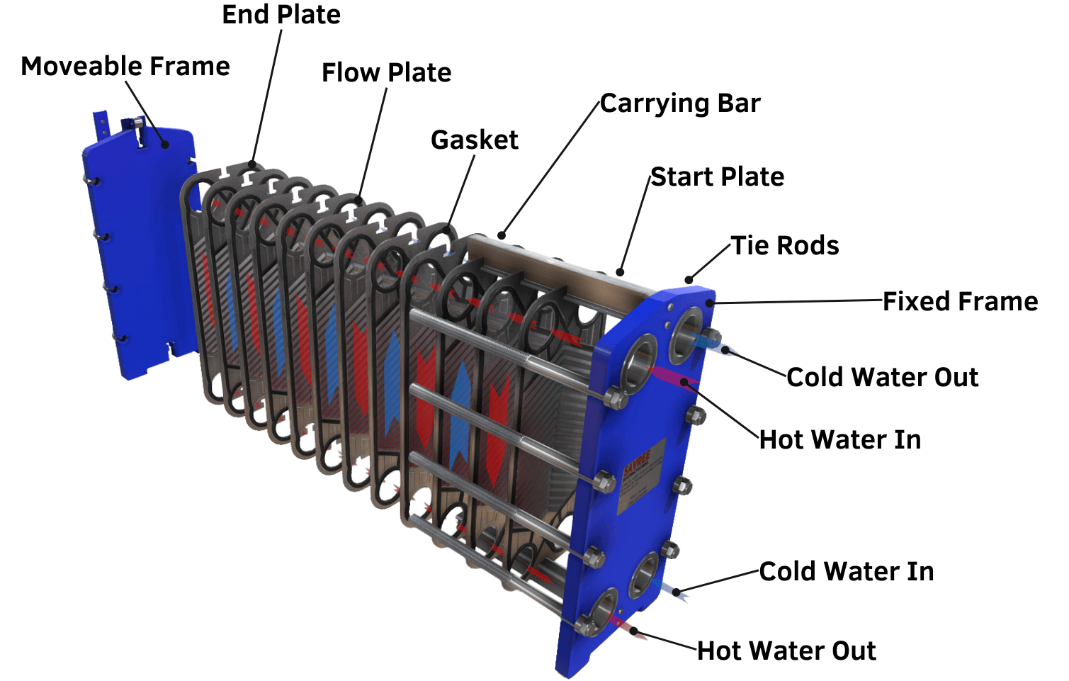
Der Verdampfer überträgt Wärme vom Prozesswasser auf das Kältemittel. Die Wärmeübertragungsrate wird bestimmt durch:
Q = U × A × LMTDWobei:
• Q = Wärmeübertragungsrate (kW)
• U = Gesamtwärmeübergangskoeffizient (kW/m²·K)
• A = Wärmeübertragungsfläche (m²)
• LMTD = Logarithmische mittlere Temperaturdifferenz (°C)
In PCB-Kühlsystemen werden häufig gelötete Plattenverdampfer verwendet, weil sie Folgendes bieten:
- Hohe Wärmeübertragungseffizienz (U-Werte von 3–6 kW/m²·K für R-410A-Verdampfer)
- Kompaktes Design (typischerweise 0,1–0,3 m² pro kW der Kapazität)
- Schnelle thermische Reaktion (typischerweise thermische Zeitkonstante). 30–60 Sekunden)
- Stabile Strömungsverteilung bei richtiger Auslegung
Die Qualität des Verdampferdesigns hat jedoch erheblichen Einfluss auf die Systemstabilität:
| Designfaktor des Verdampfers | Auswirkungen auf die PCB-Kühlung | Technische Spezifikation |
|---|---|---|
| Ungleichmäßige Strömungsverteilung | Lokale Temperaturschwankung (±0,5–2,0 °C Variation) | Druckabfallverhältnis von Anschluss zu Anschluss: 1,0–1,3 |
| Schlechtes Turbulenzdesign | Geringere Wärmeübertragungseffizienz (Reduzierung um 10–30 %) | Reynolds-Zahl: Re > 4000 (turbulent) |
| Hoher Druckabfall | Reduzierte Systemstabilität, erhöhte Pumpleistung | Typisch: 30–100 kPa pro Durchgang |
| Langsame thermische Reaktion | Process temperature lag (5–15 seconds additional delay) | Minimize liquid volume (<0.5 L per 10 kW) |
For precision PCB manufacturing, maintaining uniform thermal transfer across all channels is critical. This requires:
- Proper header design with flow nozzles or distributors
- Counter-flow configuration to maximize LMTD
- Subcooling maintenance of 3–5°C at evaporator exit
- Superheat control of 5–8°C at compressor suction
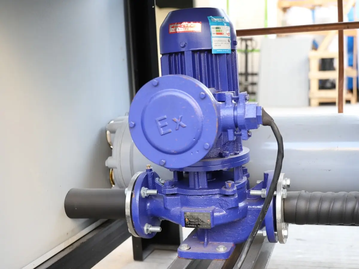
Pumpensystem: Kritische Strömungsdynamik
In PCB manufacturing, stable flow is almost as important as stable temperature. The heat transfer coefficient in process equipment is strongly dependent on flow rate:
h = Nu × k / D = C × ReM × Prn × k / DFor turbulent water flow: h ∝ Re0.8 (approximately)
Dies bedeutet, dass eine Durchflussänderung von 10 % die Wärmeübertragung um ca. 8 % beeinflussen kann.
Selbst wenn die Austrittswassertemperatur konstant bleibt, kann eine instabile Strömung die lokalen Wärmeübertragungskoeffizienten innerhalb der Anlage verändern und zu thermischen Schwingungen auf Prozessebene führen. Besonders problematisch ist dies bei:
- Galvanikbehälter: Ungleichmäßigkeit des Flusses führt zu Schwankungen der Stromdichte, die sich direkt auf die Gleichmäßigkeit der Kupferdicke auswirken (typischerweise Abweichung von ±5–15 % vom Ziel).
- Laserkühlkanäle: Strömungsschwankungen verursachen lokale Hotspots, die teure Laseroptiken beschädigen können
- Spindelkühlmäntel: Eine instabile Strömung führt zu Temperaturgradienten im Werkzeughalter, die die Bohrgenauigkeit beeinträchtigen
Moderne PCB-Kühler verwenden daher üblicherweise:
- Frequenzumrichter (VFD) bei Primärumwälzpumpen: Energieeinsparung von 30–50 % im Teillastbetrieb
- Konstantdruckregelung: Hält den Solldruck am Geräteeinlass unabhängig von Lastschwankungen aufrecht
- Durchflussüberwachungssysteme: Magnetische oder Ultraschall-Durchflussmesser mit einer Genauigkeit von ±1 %
- Mehrzonen-Hydraulikausgleich: Druckunabhängige Regelventile für jede Prozesszone
| Anwendung | Typische Durchflussrate | Druck erforderlich | Temperaturstabilität |
| Kleine CNC-Spindel (einzeln) | 3–6 l/min | 2–4 bar | ±0,5°C |
| Große CNC-Spindel | 10–20 l/min | 3–5 bar | ±0,3°C |
| Galvanikbehälter (klein) | 50–150 l/min | 1–3 bar | ±0,2°C |
| Galvanikbehälter (groß) | 200–500 l/min | 2–4 bar | ±0,1°C |
| Lasersystem | 5–15 l/min | 4–6 bar | ±0,2°C |
Wassergekühlte vs. luftgekühlte Kühler für Leiterplattenfabriken
Selecting between water-cooled and air-cooled chillers depends heavily on factory scale, operating schedule, thermal load stability requirements, and available utility infrastructure.
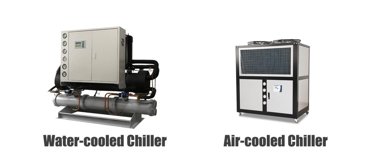
Thermodynamischer Vergleich
The fundamental difference lies in the heat rejection medium. Air-cooled systems reject heat to ambient air (specific heat capacity: 1.005 kJ/kg·K), while water-cooled systems reject heat to cooling tower water (specific heat capacity: 4.186 kJ/kg·K), approximately 4× more efficient heat transfer.
| Artikel | Wassergekühlter Kühler | Luftgekühlter Chiller |
|---|---|---|
| Cooling Stability (ΔT output) | ±0.1–0.3°C (excellent) | ±0.5–1.5°C (moderate) |
| Energieeffizienz (COP) | 4.5–6.5 (higher in large systems) | 3.0–4.5 (degraded at high ambient) |
| Komplexität der Installation | Higher (tower, pumps, piping) | Lower (direct placement) |
| Initial Investment | 20–40% higher | Lower baseline cost |
| Wartungsanforderungen | Kühlturmaufbereitung, Wassermanagement | Reinigung der Kondensatorschlange, Austausch des Filters |
| Geeigneter Kapazitätsbereich | >50 kW (optimal >150 kW) | <50 kW (optimal <150 kW) |
| Einfluss der Umgebungstemperatur | Niedrig (2–3 % pro 10 °C) | Hoch (5–8 % pro 10 °C Anstieg) |
| Wasserverbrauch | Erheblich (Verdunstungsverlust) | Minimal |
| Beste Anwendung | Massenproduktion rund um die Uhr, Präzisionsprozesse | Flexible/dezentrale Produktion, Labore |
Wassergekühlte Kühler in der großen Leiterplattenproduktion
Große Leiterplattenfabriken bevorzugen aufgrund ihrer thermischen Stabilität und Energieeffizienz im Dauerbetrieb typischerweise wassergekühlte Kühler.
Anstatt die Wärme direkt an die Luft abzugeben, übertragen wassergekühlte Systeme die Wärme über einen sekundären Wasserkreislauf, der an Kühltürme oder Trockenkühler angeschlossen ist. Dadurch entsteht ein zweistufiger Wärmeabfuhrpfad:
- Primärschleife: Prozesswasser → Verdampfer → Kompressor → Kondensator → Sekundärwasser
- Sekundärschleife: Sekundärwasser → Kühlturm (Verdunstung) oder Trockenkühler (sinnvoll) → Atmosphäre
| Parameter | Typischer Wert | Auswirkungen auf das System |
| Temperatur der Wasserversorgung des Kondensators | 25–32°C | Bestimmt den Kondensationsdruck |
| Annäherungstemperatur (Turm an Wasser) | 3–5°C | Bestimmt die Wirksamkeit des Turms |
| Kondensationstemperatur (R-410A) | 35–42°C | Beeinflusst die Arbeit des Kompressors |
| Verflüssigungsdruck (R-410A) | 18–26 bar | Höher = mehr Kompressorarbeit |
| Verbesserung des System-COP | 15–25 % gegenüber luftgekühlt | Bei typischen Umgebungsbedingungen |
Weil Wasser Wärme viel effektiver überträgt als Luft:
- Die Kondensationstemperaturen bleiben niedriger (normalerweise 35–42 °C gegenüber 45–55 °C bei luftgekühlten Geräten).
- Der Auslassdruck des Kompressors nimmt ab (geringeres Kompressionsverhältnis = weniger Arbeit)
- Der System-COP verbessert sich (normalerweise 4,5–6,5 vs. 3,0–4,5)
- Temperaturschwankungen werden reduziert (die thermische Masse des Turmbeckens sorgt für Pufferung)
- Der Verschmutzungsfaktor des Kondensators kann durch Wasseraufbereitung kontrolliert werden
Dies ist besonders wertvoll für Galvanik- und Ätzanlagen, wo große chemische Badvolumina (typischerweise 500–2000 Liter) äußerst stabile thermische Bedingungen erfordern. Die thermische Zeitkonstante großer Tanks kann überschritten werden 30 Minuten, was bedeutet, dass eine langsame, aber gleichmäßige Kühlleistung unerlässlich ist.
In Leiterplattenfabriken, die im Dauerbetrieb arbeiten, insbesondere mit einem Kühlbedarf von über 150 kW, bieten wassergekühlte Systeme im Allgemeinen eine bessere langfristige Betriebseffizienz mit typischen Amortisationszeiten von 2–4 Jahre im Vergleich zu luftgekühlten Alternativen.
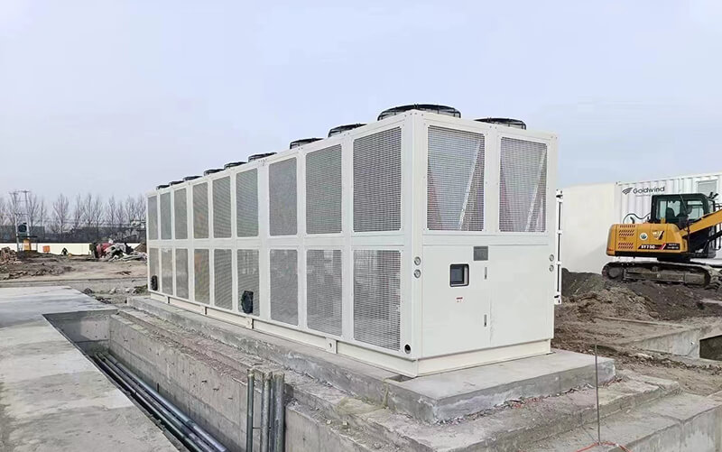
Luftgekühlte Kühler für die flexible Leiterplattenproduktion
Luftgekühlte Kältemaschinen werden häufig verwendet in:
- Produktionsanlagen für Prototypen von Leiterplatten
- Small manufacturing lines (<50 kW thermal load)
- Standalone CNC drilling machines
- Laboratory and R&D environments
- Decentralized cooling zones
- Facilities without centralized utility infrastructure
Their main advantage is simplified installation:
- No cooling tower or condenser water loop required
- Infrastructure costs reduced by 30–50%
- Installation time reduced by 40–60%
- Factory layout becomes more flexible
- No water treatment chemicals or equipment needed
However, air-cooled systems are strongly affected by ambient temperature. The cooling capacity relationship is approximately:
Kapazitätactual = Capacitybewertet × (1 – k × (Tamb - Tref))Where k ≈ 0.03–0.05 per °C above reference temperature (typically 35°C)
When outdoor temperatures rise above design conditions:
- Condenser coil temperature differential (ΔT) decreases, reducing heat rejection
- Compressor discharge pressure rises (may exceed safe limits at extreme temperatures)
- Cooling capacity drops (typically 10–15% at 40°C, 20–30% at 45°C)
- Temperature stability worsens due to variable compressor performance
- Compressor short-cycling may occur under high heat loads
This is why air-cooled systems are generally recommended for smaller thermal loads (<50 kW), facilities with adequate ventilation, or climates with mild summer temperatures (ambient typically <35°C).
Präzisionskühlung für die HDI- und Hochfrequenz-Leiterplattenproduktion
As PCB technology moves toward advanced applications, temperature stability requirements become significantly stricter:
- HDI structures: Microvia densities exceeding 100 vias/cm²
- High-frequency communication boards: Operating frequencies >28 GHz
- Automotive electronics: Reliability requirements to -40°C to +125°C
- AI server substrates: Thermal densities >50 W/cm²
- Semiconductor packaging boards: Sub-10μm registration tolerances
For high-frequency PCB materials (e.g., Rogers RO4003C, Panasonic Megtron 6), dielectric properties are temperature-sensitive:
| Material Property | Temperature Coefficient | Impact at ±1°C Deviation |
| Dielectric constant (Dk) | ±30 to ±50 ppm/°C | Impedance variation: 0.03–0.05% |
| Dissipation factor (Df) | Variable | Signal loss variation: 2–5% |
| CTE (XY plane) | 12–18 ppm/°C | Dimensional change: 0.0012–0.0018% |
Even small thermal changes can affect:
- Signal impedance: Die angestrebte Impedanztoleranz von ±5 % erfordert eine Stabilität von ±0,5 °C
- Übertragungsverlust: Die Df-Variation beeinflusst die Einfügungsdämpfung bei hohen Frequenzen
- Ebenenausrichtung: Wärmeausdehnung trägt zu Schicht-zu-Schicht-Registrierungsfehlern bei
- Dimensionsstabilität des Materials: Längenänderungen von 2–5 μm pro Meter pro °C
In der modernen Leiterplattenfertigung reichen die Anforderungen an die Temperaturstabilität aus:
ΔTStabilität = ±0,1 °C bis ±0,3 °C (für HDI/Halbleitergehäuse)
ΔTräumlich = <1,0 °C auf der gesamten Arbeitsfläche der Ausrüstung
ΔTAntwort = <5 Sekunden bis 90 % der Sollwertänderung
Um dieses Maß an Präzision zu erreichen, ist eine mehrschichtige Wärmemanagementarchitektur erforderlich:
| Systemschicht | Funktion | Temperaturregelung | Ansprechzeit |
|---|---|---|---|
| Primärkühler | Grundkühlleistung | ±1,0°C (Industriestandard) | 60–120 Sekunden |
| Sekundäre Präzisionsschleife | Feine Temperatureinstellung | ±0,1°C | 10–30 Sekunden |
| Lokale Gerätekühlung | Endgültige thermische Stabilisierung | ±0,05°C | <5 Sekunden |
| Intelligentes Steuerungssystem | Dynamische Kompensation in Echtzeit | Feedforward + Feedback | Kontinuierlich |
High-End-Systeme legen außerdem Wert auf eine geringe thermische Trägheit, was bedeutet, dass das Kühlsystem schnell auf plötzliche Änderungen der Prozesslast reagieren muss. Zu den wichtigsten Designmerkmalen gehören:
- Minimale Kältemittelfüllung: Reduziert Phasenwechselverzögerungen
- Elektronische Expansionsventile: Präzise Kältemitteldosierung (±0,5 % Genauigkeit)
- PID-Temperaturregelung: Ableitungswirkung zur Vorwegnahme von Laständerungen
- Kaskadensteuerungsarchitektur: Der Sollwert des Primärkreises wird basierend auf dem Bedarf des Sekundärkreises angepasst
Steuerungssysteme und dynamisches Wärmemanagement
Moderne PCB-Kühlsysteme basieren auf ausgefeilten Steuerungsarchitekturen, um die thermische Stabilität unter wechselnden Belastungen aufrechtzuerhalten.
Grundlagen der PID-Regelung
Der Standard-PID-Regelalgorithmus (Proportional-Integral-Derivativ) für die Temperaturregelung:
u(t) = KP × e(t) + Kich × ∫e(t)dt + KD × de(t)/dtWo:
• KP = Proportionale Verstärkung (bestimmt die Reaktionsgeschwindigkeit)
• Kich = Integrale Verstärkung (eliminiert stationären Fehler)
• KD = Differentialverstärkung (dämpft Schwingungen)
• e(t) = Fehler = Sollwert – Messwert
Typische Abstimmungsparameter für die PCB-Kühlersteuerung:
| Parameter | Typischer Bereich | Zweck |
|---|---|---|
| Proportionalband | 00,5–2,0 °C | Bestimmt die Empfindlichkeit der Steuerung |
| Integrale Zeit | 30–120 Sekunden | Eliminiert den Offset und beeinflusst die Wiederherstellungszeit |
| Ableitungszeit | 0–30 Sekunden | Reduziert Überschwinger, dämpft Schwingungen |
| Zykluszeit | 2–10 Sekunden | Zur digitalen Ausgangsumschaltung |
Erweiterte Kontrollstrategien
- Adaptive Steuerung: Passt die PID-Parameter automatisch an die Betriebsbedingungen und Laständerungen an
- Feedforward-Steuerung: Verwendet gemessene Lastsignale (z. B. Laserleistung, Spindelgeschwindigkeit), um den thermischen Bedarf vorherzusagen
- Kaskadensteuerung: Der Primärkreislauf regelt den Verflüssigungsdruck; Der Sekundärkreis regelt die Prozesstemperatur
- Fuzzy-Logic-Steuerung: Handles non-linearities and provides robust performance across operating range
- Machine Learning Optimization: Analyzes historical data to predict optimal setpoints and anticipate disturbances
Überlegungen zur Energieeffizienz bei der PCB-Kühlung
Cooling systems often account for 15–30% of total energy consumption in PCB factories, making efficiency optimization economically significant.
Energieoptimierungstechnologien
| Technologie | Mechanismus | Typische Energieeinsparungen | ROI Period |
|---|---|---|---|
| Variable Frequency Drive (VFD) | Matches compressor speed to cooling demand | 20–40% at part-load | 2–3 years |
| Floating Condensing Pressure | Adjusts condensing setpoint based on ambient | 5–15% seasonally | 1–2 years |
| Intelligent Load Matching | Predictive capacity allocation across chillers | 10–25% | 2–4 Jahre |
| Variable Flow Pumping | Matches pump speed to system demand | 30–50% at part-load | 2–3 years |
| Wärmerückgewinnung | Captures waste heat for facility use | 10–30% of heating load | 3–5 years |
| Multi-Stage Control | Optimizes compressor staging | 5–10 % | 1–2 years |
Kennzahlen zur Energieleistung
| KPI | Definition | Typischer Wert |
| COP (Leistungskoeffizient) | Cooling capacity / Compressor power | 3.5–6.0 |
| IPLV (Integrated Part Load Value) | Weighted average efficiency at various loads | 4.0–6.5 kW/ton |
| kW/ton Ratio | Power consumption per ton of refrigeration | 0.5–0.9 kW/ton |
| Chiller Efficiency (EER) | British Thermal Units per watt-hour | 12–20 BTU/Wh |
In large-scale 24/7 PCB factories, optimizing cooling efficiency through the measures above can reduce operational costs by $50,000–$200,000 annually per 100 kW of cooling capacity.
Kühlstrategie auf Systemebene in modernen Leiterplattenfabriken
Modern PCB plants rarely rely on a single cooling system. Instead, they use layered thermal management architectures that address the diverse thermal requirements across the facility.
Zentralisierte vs. verteilte Architektur
| Architecture | Vorteile | Nachteile | Am besten für |
|---|---|---|---|
| Centralized (Large Central Plant) | Higher efficiency, easier maintenance, better redundancy | Higher initial cost, complex piping, single failure risk | Large facilities (>50,000 m²) |
| Distributed (Multiple Unit Coolers) | Simpler installation, easier expansion, fault isolation | Higher maintenance burden, less efficient overall | Small-medium facilities, flexible layouts |
| Hybrid (Central + Dedicated) | Optimal balance of efficiency and flexibility | More complex control integration | Most modern PCB factories |
Typische Systemkonfiguration
- Centralized cooling stations: Provide baseline factory load (50–70% of total capacity), operating at optimized setpoints
- Dedicated precision chillers: Serve critical equipment (electroplating, laser drilling) with tighter temperature control
- Separate temperature zones: Independent loops for wet processes (electroplating, etching) and dry processes (drilling, AOI)
- Backup redundancy systems: N+1 or 2N redundancy for critical production lines (typically 10–20% excess capacity)
- Heat recovery loops: Capture waste heat for building heating or domestic hot water
Prozessspezifische Kühlstrategien
- Electroplating lines: Prioritize chemical temperature stability (±0.2°C). Large thermal mass requires slow, steady control with minimal cycling. Recirculation pump control critical for uniform flow distribution.
- CNC drilling: Focus on dimensional control at drill tip. Individual spindle cooling with dedicated flow circuits. Real-time temperature monitoring at tool-workpiece interface.
- AOI systems: Require optical stability. Lighting temperature affects colorimetry and contrast. Environmental chamber control may supplement chiller cooling.
- Laser drilling systems: Require localized high-precision cooling for optics (often <±0.1°C). Separate cooling circuits for laser source and optics train. Fast-responding heat exchangers to prevent thermal lensing.
- Lamination presses: Zone temperature control across platen surface. Multiple independently controlled heating/cooling zones. Integrated thermostatic mixing valves.
Because different processes behave differently thermally, PCB cooling design must be approached from a system engineering perspective rather than simple equipment selection. This includes:
- Thermal load mapping across the facility
- Hydraulic network analysis for flow distribution
- Dynamic simulation of thermal interactions
- Control strategy integration across all subsystems
Best Practices für Wartung und Betrieb
Sustainable cooling system performance requires proactive maintenance practices:
| Wartungsaufgabe | Frequenz | Impact of Neglect |
|---|---|---|
| Water quality testing and treatment | Monthly | Scale buildup, microbiological growth, corrosion |
| Condenser coil cleaning (air-cooled) | Quarterly | Capacity loss of 5–15% per year |
| Cooling tower water treatment | Continuous + monthly analysis | Scale, corrosion, Legionella risk |
| Refrigerant leak inspection | Quarterly | Capacity loss, environmental impact |
| Compressor oil analysis | 6–12 months | Early wear detection |
| Control system calibration | Annual | Temperature drift, instability |
| Pump and valve inspection | 6 months | Flow instability, system imbalance |
Abschluss
The best cooling solution for PCB manufacturing depends on process characteristics, production scale, and precision requirements.
Wassergekühlte Chiller provide excellent thermal stability (typically ±0,1–0,3 °C) and superior energy efficiency (COP 4.5–6.5) for large continuous-production PCB factories. They are optimal for facilities with >150 kW cooling demand operating 24/7, particularly those with precision electroplating and HDI manufacturing.
Luftgekühlte Kältemaschinen offer flexible installation, lower infrastructure costs, and simpler maintenance for smaller or decentralized applications. They are best suited for facilities with <50 kW thermal load, mild climate conditions, or requirements for frequent layout changes.
Precision cooling systems are essential for HDI, high-frequency, and semiconductor packaging PCB manufacturing where thermal fluctuations directly affect electrical performance and dimensional accuracy. These require multi-stage control architectures achieving ±0.1°C or tighter temperature stability.
Ultimately, PCB cooling is not simply about removing heat. It is about maintaining long-term thermal stability across complex and constantly changing production environments through:
- Proper system architecture matched to process requirements
- Component selection prioritizing reliability and efficiency
- Advanced control strategies for dynamic load management
- Proactive maintenance to sustain performance over time
A properly engineered cooling system improves:
- Product consistency: Reduced dimensional and electrical variation
- Yield rate: Fewer thermal-related defects
- Lebensdauer der Ausrüstung: Reduced thermal stress on components
- Produktionseffizienz: Reduced rework and downtime
- Energy performance: Lower operational costs
As PCB technology continues evolving toward higher precision (sub-10μm features), higher density (>20 layers, >500 I/O), and higher frequencies (>70 GHz), industrial cooling systems will play an increasingly critical role in manufacturing stability and product reliability. The thermal management system must be considered as a core process enabler, not merely auxiliary infrastructure.