
При производстве печатных плат контроль температуры напрямую влияет на качество продукции, стабильность процесса и эффективность производства. В отличие от обычных промышленных систем охлаждения, производство печатных плат включает в себя несколько термочувствительных процессов, выполняемых одновременно, включая сверление с ЧПУ, гальваническое покрытие, травление, ламинирование, экспонирование и контроль AOI. Каждый процесс имеет разные тепловые характеристики, колебания нагрузки и требования к температурной стабильности.
Проблема управления температурным режимом при изготовлении печатных плат характеризуется многоточечная термомуфта, где соседнее технологическое оборудование может взаимно влиять на тепловую среду друг друга. Такое пространственное тепловое взаимодействие требует тщательного проектирования на уровне системы, а не изолированных решений по охлаждению на уровне оборудования.
По этой причине системы охлаждения печатных плат предназначены не только для отвода тепла. Их настоящая цель — поддерживать стабильную тепловую среду на протяжении всего производственного процесса, компенсируя как установившиеся тепловые нагрузки а также переходные тепловые возмущения.
В современном производстве печатных плат высокой плотности и HDI даже небольшие колебания температуры могут привести к отклонению размеров (обычно допуск ±0,02 мм для плат HDI), неравномерному нанесению меди, проблемам с целостностью сигнала или ошибкам многослойного выравнивания. Поскольку плотность плат и частота сигналов продолжают расти, системы охлаждения становятся частью самого технологического процесса, а не вспомогательного заводского оборудования.
Тепловые характеристики процессов производства печатных плат
На разных этапах производства печатных плат тепло выделяется по-разному. Понимание этого теплового поведения, включая механизмы тепловыделения, тепловые постоянные времени и допустимые температурные диапазоны, является основой выбора правильного решения для охлаждения.
| Процесс печатной платы | Основной источник тепла | Цель охлаждения | Типичная тепловая нагрузка | Чувствительность к температуре | Допустимое изменение |
|---|---|---|---|---|---|
| Сверление с ЧПУ | Трение шпинделя, интерфейс бит-подложка | Уменьшить тепловое расширение | 1,5–4,0 кВт на шпиндель | Очень высокий | ±0,5°С |
| Гальваника | Фарадеевское сопротивление, джоулевой нагрев | Стабилизировать толщину покрытия | 8–25 кВт на бак (в зависимости от размера бака) | Чрезвычайно высокий | ±0,2–0,5°С |
| Офорт | Экзотермические химические реакции, воздействие распыления | Поддерживайте последовательность реакций | 3–12 кВт на секцию линии | Высокий | ±1,0°С |
| Ламинирование | Пресс-плиты, отверждение экзотермы | Предотвращение коробления платы, контроль профиля отверждения | 15–50 кВт на пресс | Высокий | ±2,0°C (однородность зоны) |
| Лазерное сверление (CO₂/УФ) | Отходящее тепло лазерного источника, аблированный материал | Защитите оптику, предотвратите переплавку смолы | 2–8 кВт на лазерный блок | Очень высокий | ±0,3°С |
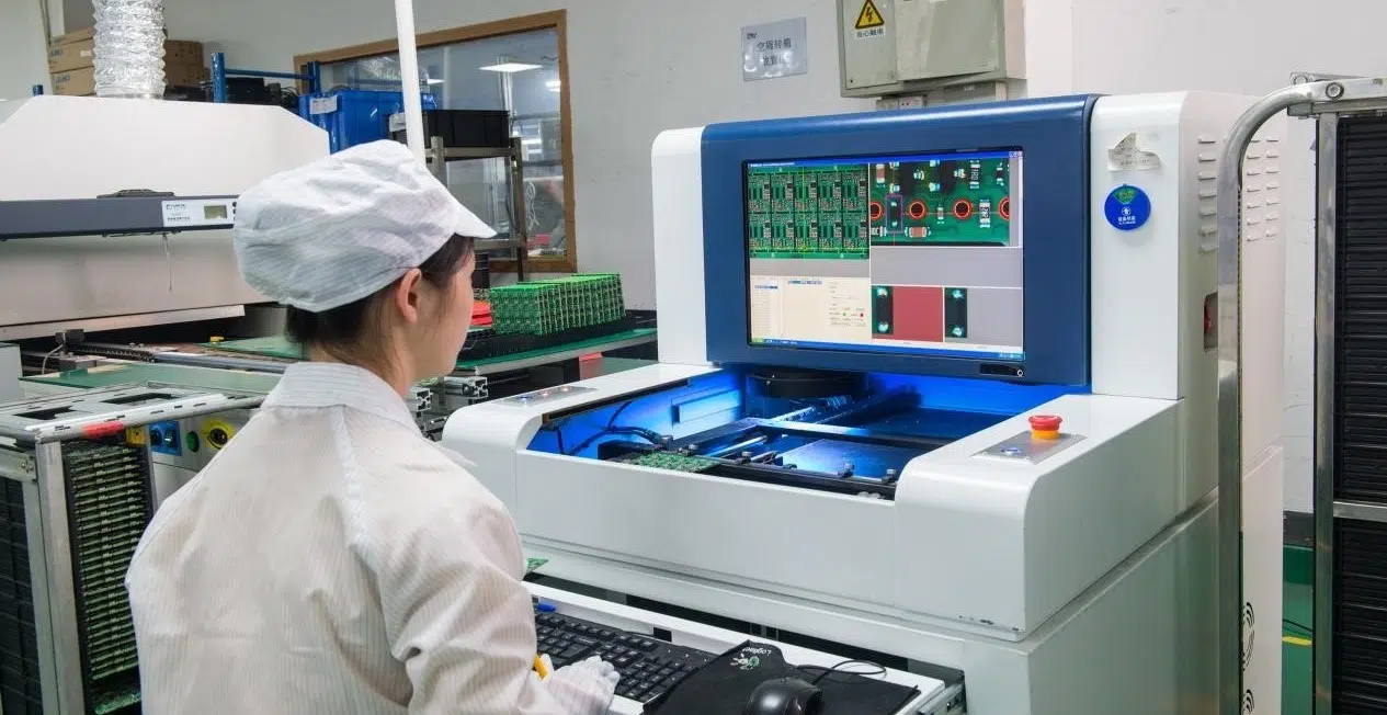
| АОИ / Инспекция | Системы освещения, камеры, процессоры | Поддерживать стабильность оптического пути | 00,5–2,0 кВт на систему | Середина | ±2,0°С |
Термическая динамика в механическом бурении
В процессах механического сверления скорость шпинделя часто превышает 100 000 об/мин (обычно 120 000–200 000 об/мин для микросверления). Трение между сверлами и подложками печатных плат приводит к локализованному нагреву на границе сверл. Плотность теплового потока может достигать 10–50 Вт/мм² во время агрессивных циклов бурения.
Это локализованное тепловое воздействие создает две основные проблемы:
- Термомеханическое напряжение: Дифференциальное тепловое расширение между сверлом (обычно карбидом вольфрама с α ≈ 4,9×10⁻⁶/°C) и подложкой печатной платы (FR-4 с α ≈ 12–18×10⁻⁶/°C) вызывает микротрещины на стенках отверстия.
- Размазывание смолы**: повышенные температуры (обычно >150°C на кончике сверла) размягчают и оплавляют эпоксидную смолу, которая затем размазывается по стволу и стенкам отверстия, нарушая целостность стенок ствола.
Это становится особенно важным для плат HDI, где допуски на микроотверстия обычно невелики. ±0,020 мм (20 мкм), что требует температурной стабильности ниже 0,5°C в зоне сверления.
Термическая электрохимия в гальванике и травлении
В линиях гальваники и травления термическое поведение в большей степени обусловлено химическими факторами. Температура напрямую влияет:
- Плотность тока обмена: Согласно уравнению Батлера-Фольмера, кинетика реакции экспоненциально зависит от температуры (обычно 2–3% на каждый градус Цельсия при осаждении меди).
- Проводимость электролита: Ионная проводимость увеличивается примерно на 2% при повышении температуры.
- Коэффициент диффузии: Скорость массового переноса увеличивается с температурой, что влияет на бросающую способность и однородность.
Чрезмерно высокие температуры могут временно повысить скорость реакции, но часто ухудшают консистенцию покрытия и стабильность процесса. Для кислотного меднения оптимальный температурный диапазон обычно составляет 22–28°С, с чувствительностью к скорости осаждения примерно ±0,05 мкм/мин на отклонение °C.
Термомеханические проблемы при ламинировании
Ламинирование создает еще один тип термической проблемы, связанной с температура стеклования (Tg) материала ламината. Во время нажатия:
- Ламинат нагревается выше температуры Tg (обычно 130–180°C для материалов с высокой Tg).
- Течение смолы и отверждение B-стадии происходят в узком температурном диапазоне.
- Неравномерное охлаждение после прессования создает температурные градиенты по толщине.
Остаточная термическая нагрузка из-за неравномерного охлаждения (обычно разница температур 5–15°C по всей панели) может привести к значения изгиба и скручивания превышают 0,5%, что приводит к проблемам с последующей регистрацией в процессах бурения и построения изображений.
Термодинамика системы охлаждения с замкнутым контуром
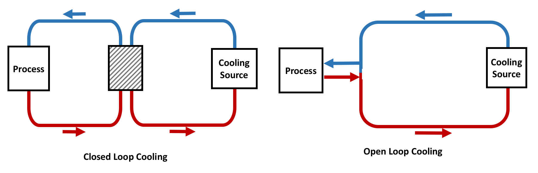
Большинство современных заводов по производству печатных плат используют промышленные охладители с замкнутым контуром, поскольку они обеспечивают стабильный и изолированный тепловой контроль. Понимание холодильного цикла с компрессией пара необходимо для правильной спецификации системы.
КС = Qиспариться / Вткомп = час1 – ч4 / ч2 – ч1Для типичных охладителей печатных плат COP колеблется в пределах 3,0–6,5 в зависимости от условий эксплуатации.
Анализ цикла сжатия пара
В стандартном парокомпрессионном холодильном цикле, используемом в чиллерах для печатных плат:
- Сжатие (1→2): Пары хладагента низкого давления сжимаются до высокого давления. Для систем R-410A это обычно повышает давление с ~9 бар (насыщенный пар при 0°C) до ~26 бар (насыщенный пар при 45°C).
- Конденсат (2→3): Пар под высоким давлением и высокой температурой выделяет тепло и конденсируется. Обычно поддерживается температура переохлаждения 3–8°C, чтобы гарантировать отсутствие попадания пара в расширительное устройство.
- Расширение (3→4): Жидкий хладагент проходит через дросселирующее устройство (термостатический расширительный клапан или электронный расширительный клапан), падая до низкого давления.
- Испарение (4→1): Жидкостно-паровая смесь низкого давления поглощает тепло технологической воды, испаряясь до насыщенного пара.
| холодильный | ПГП | Типичное рабочее давление (бар) | Объемная холодопроизводительность |
| R-410A | 2088 | 9–26 (испарение/кондиционирование) | Высокий (предпочтителен для средних и больших систем) |
| Р-134а | 1430 | 3–12 | Умеренный (меньшие системы) |
| Р-513А | 573 | 4–14 | Умеренный (альтернатива с более низким ПГП) |
| Р-1234зе | 1 | 4–13 | Нижний (будущий вариант с низким ПГП) |
Преимущества системы с замкнутым контуром
В замкнутой системе:
- Технологическая вода циркулирует независимо от внешней среды, предотвращая загрязнение переносимыми по воздуху частицами и микроорганизмами.
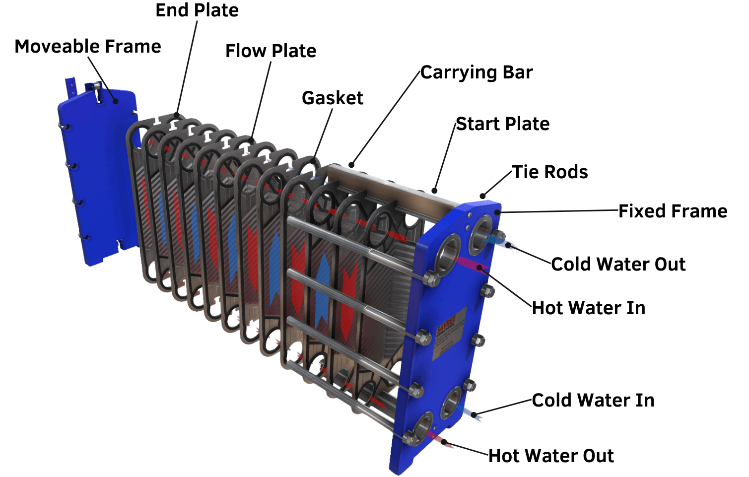
- Теплообмен происходит через пластинчатые теплообменники с типичной эффективностью 85–95%
- Риск загрязнения воды снижается за счет фильтрации и очистки воды.
- Регулирование температуры становится более предсказуемым благодаря постоянному массовому расходу воды и известным термическим свойствам.
- Конструкция с замкнутым контуром обеспечивает точный контроль качества воды (обычно поддерживается при удельном сопротивлении > 1 МОм·см для прецизионных применений).
По сравнению с открытыми системами охлаждения конструкции с замкнутым контуром обеспечивают:
- Лучшая температурная стабильность (обычно ±0,1–0,5°C по сравнению с ±1,0–3,0°C для открытых систем)
- Меньшая частота технического обслуживания (без образования накипи в дрейфующей башне и роста водорослей)
- Уменьшение образования накипи и загрязнения в технологических теплообменниках.
- Увеличенный срок службы оборудования благодаря контролируемому химическому составу воды
Основные компоненты системы охлаждения печатной платы
Компрессор: динамическое управление холодопроизводительностью
Компрессор является основным источником энергии холодильной системы, обычно потребляя 25–40 % от общей мощности чиллера.

| Тип компрессора | Диапазон мощности | Эффективность при частичной нагрузке | Уровень шума | Лучшее приложение |
| Прокрутка (фиксированная скорость) | 5–50 кВт | Плохо при загрузке <50% | Низкий | Постоянная нагрузка, небольшие системы |
| Прокрутка (Инвертор) | 5–70 кВт | Отлично (20–100 % емкости) | Умеренный | Переменная нагрузка, большинство чиллеров для печатных плат |
| Винт (фиксированная скорость) | 50–300 кВт | Умеренный | Высокий | Большие системы с постоянной нагрузкой |
| Винт (инвертор/ЧРП) | 50–500 кВт | Отличный | Высокий | Большие системы переменной нагрузки |
| Центробежный | >300 кВт | Хороший | Умеренный | Очень крупные центральные растения |
В современных приложениях для печатных плат широко используются инверторные компрессоры (приводы с регулируемой частотой), поскольку производственные нагрузки постоянно меняются. Машины часто запускаются и останавливаются, нагрузка на химическую ванну колеблется, а буровые системы работают с перерывами, рабочий цикл обычно варьируется от 30–80%.
Компрессоры с переменной частотой позволяют системе охлаждения:
- Уменьшите превышение температуры (обычно 00,5°С по сравнению с 2–3°C для управления включением/выключением)
- Повышение энергоэффективности (обычно Экономия энергии 20–35 % в условиях частичной нагрузки)
- Поддерживайте стабильную температуру воды на выходе (обычно ±0,1–0,3°С стабильность)
- Снижение нагрузки на компрессор при циклическом включении (снижение частоты запуска на 60–80%)
Традиционные системы с фиксированной скоростью и циклическими включениями и выключениями испытывают трудности при нестабильной нагрузке на производство печатных плат, что приводит к:
- Колебания температуры с амплитудой 2–5°С.
- Пусковой ток двигателя компрессора 5–7× номинальный ток
- Повышенный механический износ (типичное сокращение срока службы подшипников на 30–50 %).
Испаритель: стабильность теплообмена
Испаритель передает тепло от технологической воды хладагенту. Скорость теплопередачи регулируется:
Q = U × A × LMTDГде:
• Q = Скорость теплопередачи (кВт)
• U = общий коэффициент теплопередачи (кВт/м²·К)
• A = площадь поверхности теплопередачи (м²)
• LMTD = средняя логарифмическая разница температур (°C).
В системах охлаждения печатных плат обычно используются паяные пластинчатые испарители, поскольку они обеспечивают:
- Высокая эффективность теплопередачи (значения U 3–6 кВт/м²·К для испарителей R-410А)
- Компактный дизайн (обычно 00,1–0,3 м² на кВт емкости)
- Быстрый тепловой отклик (обычно тепловая постоянная времени) 30–60 секунд)
- Стабильное распределение потока при правильной конструкции
Однако качество конструкции испарителя существенно влияет на стабильность системы:
| Расчетный коэффициент испарителя | Влияние на охлаждение печатной платы | Инженерная спецификация |
|---|---|---|
| Неравномерное распределение потока | Локальные колебания температуры (колебание ±0,5–2,0°C) | Коэффициент падения давления между портами: 1,0–1,3. |
| Плохая конструкция турбулентности | Более низкая эффективность теплопередачи (снижение на 10–30 %) | Число Рейнольдса: Re > 4000 (турбулентный) |
| Высокое падение давления | Снижение стабильности системы, увеличение мощности накачки | Типичное: 30–100 кПа за проход. |
| Медленный тепловой отклик | Задержка температуры процесса (дополнительная задержка 5–15 секунд) | Минимизируйте объем жидкости (<0,5 л на 10 кВт) |
Для прецизионного производства печатных плат критически важно поддерживать равномерную теплопередачу по всем каналам. Для этого необходимо:
- Правильный дизайн заголовка с сопла или распределители потока
- Конфигурация противотока для максимизации LMTD
- Поддержание переохлаждения 3–5°С на выходе из испарителя
- Контроль перегрева 5–8°С на всасывании компрессора
Насосная система: критическая динамика потока
При производстве печатных плат стабильный поток почти так же важен, как и стабильная температура. Коэффициент теплопередачи в технологическом оборудовании сильно зависит от скорости потока:
h = Nu × k / D = C × Reм × Прн × k/D Для турбулентного течения воды: h ∝ Re0.8 (примерно)
Это означает, что изменение расхода на 10 % может повлиять на теплообмен примерно на 8 %.
Даже если температура воды на выходе остается постоянной, нестабильный поток может изменить локальные коэффициенты теплопередачи внутри оборудования, что приведет к тепловым колебаниям на уровне процесса. Это особенно проблематично в:
- Гальванические резервуары: Неравномерность потока приводит к изменению плотности тока, что напрямую влияет на однородность толщины меди (обычно отклонение от заданного значения составляет ±5–15%).
- Каналы лазерного охлаждения: Изменения потока вызывают появление локальных горячих точек, которые могут повредить дорогую лазерную оптику.
- Рубашки охлаждения шпинделя: Нестабильный поток приводит к перепаду температур в держателе инструмента, что влияет на точность сверления.
Поэтому в современных чиллерах для печатных плат обычно используются:
- Частотно-регулируемые приводы (ЧРП) на первичных циркуляционных насосах: экономия энергии 30–50 % при частичной нагрузке.
- Контроль постоянного давления: Поддерживает заданное давление на входе оборудования независимо от колебаний нагрузки.
- Системы мониторинга потока: Магнитные или ультразвуковые расходомеры с точностью ±1 %.
- Многозонная гидравлическая балансировка: Независимые от давления регулирующие клапаны для каждой технологической зоны
| Приложение | Типичный расход | Требуемое давление | Температурная стабильность |
| Малый шпиндель с ЧПУ (одиночный) | 3–6 л/мин | 2–4 бар | ±0,5°С |
| Большой шпиндель с ЧПУ | 10–20 л/мин | 3–5 бар | ±0,3°С |
| Гальванический бак (маленький) | 50–150 л/мин | 1–3 бар | ±0,2°С |
| Гальванический бак (большой) | 200–500 л/мин | 2–4 бар | ±0,1°С |
| Лазерная система | 5–15 л/мин | 4–6 бар | ±0,2°С |
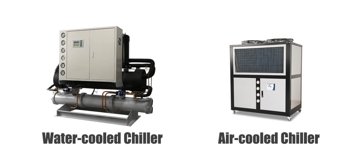
Чиллеры с водяным и воздушным охлаждением для заводов по производству печатных плат
Выбор между чиллерами с водяным и воздушным охлаждением во многом зависит от масштаба предприятия, графика работы, требований к стабильности тепловой нагрузки и доступной коммунальной инфраструктуры.
Термодинамическое сравнение
The fundamental difference lies in the heat rejection medium. Air-cooled systems reject heat to ambient air (specific heat capacity: 1.005 kJ/kg·K), while water-cooled systems reject heat to cooling tower water (specific heat capacity: 4.186 kJ/kg·K), approximately 4× more efficient heat transfer.
| Элемент | Чиллер с водяным охлаждением | Чиллер с воздушным охлаждением |
|---|---|---|
| Cooling Stability (ΔT output) | ±0.1–0.3°C (excellent) | ±0.5–1.5°C (moderate) |
| Энергоэффективность (КПД) | 4.5–6.5 (higher in large systems) | 3.0–4.5 (degraded at high ambient) |
| Сложность установки | Higher (tower, pumps, piping) | Lower (direct placement) |
| Initial Investment | 20–40% higher | Lower baseline cost |
| Требования к техническому обслуживанию | Cooling tower treatment, water management | Condenser coil cleaning, filter replacement |
| Suitable Capacity Range | >50 kW (optimal >150 kW) | <50 kW (optimal <150 kW) |
| Ambient Temperature Influence | Низкая (2–3% на 10°C) | Высокая (5–8% на каждые 10°C повышения) |
| Water Consumption | Значительные (потери на испарение) | Минимальный |
| Лучшее приложение | Массовое производство 24/7, точные процессы | Гибкое/децентрализованное производство, лаборатории |
Чиллеры с водяным охлаждением при крупном производстве печатных плат
Крупные заводы по производству печатных плат обычно отдают предпочтение чиллерам с водяным охлаждением из-за их термической стабильности и энергоэффективности при непрерывной работе.
Вместо того, чтобы отводить тепло непосредственно в воздух, системы с водяным охлаждением передают тепло через вторичный водяной контур, подключенный к градирням или сухим градирням. Это создает двухступенчатый путь отвода тепла:
- Первичный цикл: Технологическая вода → Испаритель → Компрессор → Конденсатор → Вторичная вода
- Вторичный контур: Вторичная вода → Градирня (испарительная) или сухой охладитель (разумная) → Атмосфера
| Параметр | Типичное значение | Влияние на систему |
| Температура воды на подаче конденсатора | 25–32°С | Determines condensing pressure |
| Approach temperature (tower to water) | 3–5°С | Determines tower effectiveness |
| Condensing temperature (R-410A) | 35–42°C | Affects compressor work |
| Condensing pressure (R-410A) | 18–26 bar | Higher = more compressor work |
| System COP improvement | 15–25% vs air-cooled | At typical ambient conditions |
Because water transfers heat much more effectively than air:
- Condensing temperatures remain lower (typically 35–42°C vs. 45–55°C for air-cooled)
- Compressor discharge pressure decreases (lower compression ratio = less work)
- System COP improves (typically 4.5–6.5 vs. 3,0–4,5)
- Temperature fluctuations are reduced (tower bassin’s thermal mass provides buffering)
- Condenser fouling factor can be managed through water treatment
Это особенно ценно для линий гальваники и травления, где большие объемы химических ванн (обычно 500–2000 литров) требуют чрезвычайно стабильных тепловых условий. Термическая постоянная времени больших резервуаров может превышать 30 минутЭто означает, что важно медленное, но стабильное охлаждение.
На заводах по производству печатных плат, работающих непрерывно, особенно при потребности в охлаждении свыше 150 кВт, системы с водяным охлаждением обычно обеспечивают более высокую долгосрочную эксплуатационную эффективность с типичным сроком окупаемости 2–4 года по сравнению с альтернативами с воздушным охлаждением.
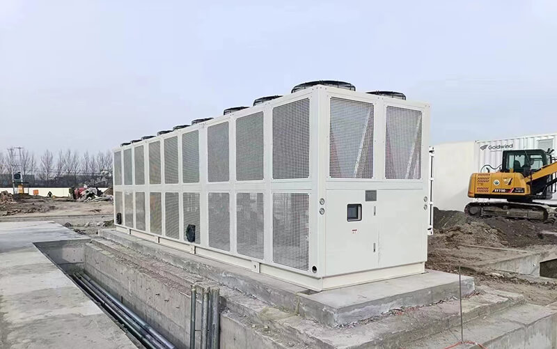
Чиллеры с воздушным охлаждением для производства гибких печатных плат
Чиллеры с воздушным охлаждением обычно используются в:
- Производство прототипов печатных плат
- Небольшие производственные линии (тепловая нагрузка <50 кВт)
- Автономные сверлильные станки с ЧПУ
- Лаборатория и среда исследований и разработок
- Децентрализованные зоны охлаждения
- Объекты без централизованной инженерной инфраструктуры
Their main advantage is simplified installation:
- No cooling tower or condenser water loop required
- Infrastructure costs reduced by 30–50%
- Installation time reduced by 40–60%
- Factory layout becomes more flexible
- No water treatment chemicals or equipment needed
However, air-cooled systems are strongly affected by ambient temperature. The cooling capacity relationship is approximately:
Емкостьactual = Capacityрейтинг × (1 – k × (Tamb – Тref))Where k ≈ 0.03–0.05 per °C above reference temperature (typically 35°C)
When outdoor temperatures rise above design conditions:
- Condenser coil temperature differential (ΔT) decreases, reducing heat rejection
- Compressor discharge pressure rises (may exceed safe limits at extreme temperatures)
- Cooling capacity drops (typically 10–15% at 40°C, 20–30% at 45°C)
- Temperature stability worsens due to variable compressor performance
- Compressor short-cycling may occur under high heat loads
This is why air-cooled systems are generally recommended for smaller thermal loads (<50 kW), facilities with adequate ventilation, or climates with mild summer temperatures (ambient typically <35°C).
Прецизионное охлаждение для HDI и производства высокочастотных печатных плат
As PCB technology moves toward advanced applications, temperature stability requirements become significantly stricter:
- HDI structures: Microvia densities exceeding 100 vias/cm²
- High-frequency communication boards: Operating frequencies >28 GHz
- Automotive electronics: Reliability requirements to -40°C to +125°C
- AI server substrates: Thermal densities >50 W/cm²
- Semiconductor packaging boards: Sub-10μm registration tolerances
For high-frequency PCB materials (e.g., Rogers RO4003C, Panasonic Megtron 6), dielectric properties are temperature-sensitive:
| Material Property | Temperature Coefficient | Impact at ±1°C Deviation |
| Dielectric constant (Dk) | ±30 to ±50 ppm/°C | Impedance variation: 0.03–0.05% |
| Dissipation factor (Df) | Переменная | Signal loss variation: 2–5% |
| CTE (XY plane) | 12–18 ppm/°C | Dimensional change: 0.0012–0.0018% |
Even small thermal changes can affect:
- Signal impedance: Target impedance tolerance of ±5% requires ±0.5°C stability
- Transmission loss: Df variation affects insertion loss at high frequencies
- Layer alignment: Thermal expansion contributes to layer-to-layer registration errors
- Material dimensional stability: Length changes of 2–5μm per meter per °C
In advanced PCB manufacturing, temperature stability requirements reach:
ΔТстабильность = ±0.1°C to ±0.3°C (for HDI/semiconductor packaging)
ΔТspatial = <1.0°C across equipment work surface
ΔТresponse = <5 seconds to 90% of setpoint change
Achieving this level of precision requires a multi-layer thermal management architecture:
| System Layer | Function | Контроль температуры | Время ответа |
|---|---|---|---|
| Primary Chiller | Baseline cooling capacity | ±1.0°C (industrial standard) | 60–120 seconds |
| Secondary Precision Loop | Fine temperature adjustment | ±0,1°С | 10–30 seconds |
| Local Equipment Cooling | Final thermal stabilization | ±0,05°С | <5 секунд |
| Intelligent Control System | Real-time dynamic compensation | Feedforward + feedback | Continuous |
High-end systems also emphasize low thermal inertia, meaning the cooling system must respond quickly to sudden process load changes. Key design features include:
- Minimal refrigerant charge: Reduces phase change delays
- Электронные расширительные клапаны: Precise refrigerant metering (±0.5% accuracy)
- ПИД-регулятор температуры: Derivative action to anticipate load changes
- Cascade control architecture: Primary loop setpoint adjusted based on secondary loop demand
Системы управления и динамическое управление температурным режимом
Modern PCB cooling systems rely on sophisticated control architectures to maintain thermal stability under varying loads.
Основы ПИД-регулирования
The standard PID (Proportional-Integral-Derivative) control algorithm for temperature regulation:
и(т) = Кп × е(т) + Кя × ∫e(t)dt + Kд × de(t)/dtWhere:
• Кп = Proportional gain (determines response speed)
• Кя = Integral gain (eliminates steady-state error)
• Кд = Derivative gain (damps oscillations)
• e(t) = Error = Setpoint – Measured value
Typical tuning parameters for PCB chiller control:
| Параметр | Типичный диапазон | Цель |
|---|---|---|
| Пропорциональный диапазон | 0.5–2.0°C | Determines control sensitivity |
| Integral Time | 30–120 секунд | Eliminates offset, affects recovery time |
| Derivative Time | 0–30 секунд | Reduces overshoot, damps oscillations |
| Cycle Time | 2–10 seconds | For digital output switching |
Расширенные стратегии управления
- Adaptive Control: Automatically adjusts PID parameters based on operating conditions and load changes
- Feedforward Control: Uses measured load signals (e.g., laser power, spindle speed) to anticipate thermal demand
- Cascade Control: Primary loop controls condensing pressure; secondary loop controls process temperature
- Fuzzy Logic Control: Handles non-linearities and provides robust performance across operating range
- Machine Learning Optimization: Analyzes historical data to predict optimal setpoints and anticipate disturbances
Вопросы энергоэффективности при охлаждении печатных плат
Cooling systems often account for 15–30% of total energy consumption in PCB factories, making efficiency optimization economically significant.
Технологии оптимизации энергетики
| Технология | Механизм | Типичная экономия энергии | ROI Period |
|---|---|---|---|
| Variable Frequency Drive (VFD) | Matches compressor speed to cooling demand | 20–40% at part-load | 2–3 years |
| Floating Condensing Pressure | Adjusts condensing setpoint based on ambient | 5–15% seasonally | 1–2 years |
| Intelligent Load Matching | Predictive capacity allocation across chillers | 10–25% | 2–4 года |
| Variable Flow Pumping | Matches pump speed to system demand | 30–50% at part-load | 2–3 years |
| Рекуперация тепла | Captures waste heat for facility use | 10–30% of heating load | 3–5 years |
| Multi-Stage Control | Optimizes compressor staging | 5–10% | 1–2 years |
Показатели энергоэффективности
| KPI | Определение | Типичное значение |
| COP (коэффициент производительности) | Cooling capacity / Compressor power | 3.5–6.0 |
| IPLV (Integrated Part Load Value) | Weighted average efficiency at various loads | 4.0–6.5 kW/ton |
| kW/ton Ratio | Power consumption per ton of refrigeration | 0.5–0.9 kW/ton |
| Chiller Efficiency (EER) | British Thermal Units per watt-hour | 12–20 BTU/Wh |
In large-scale 24/7 PCB factories, optimizing cooling efficiency through the measures above can reduce operational costs by $50,000–$200,000 annually per 100 kW of cooling capacity.
Стратегия охлаждения на уровне системы на современных заводах по производству печатных плат
Modern PCB plants rarely rely on a single cooling system. Instead, they use layered thermal management architectures that address the diverse thermal requirements across the facility.
Централизованная и распределенная архитектура
| Architecture | Преимущества | Недостатки | Лучшее для |
|---|---|---|---|
| Centralized (Large Central Plant) | Higher efficiency, easier maintenance, better redundancy | Higher initial cost, complex piping, single failure risk | Large facilities (>50,000 m²) |
| Distributed (Multiple Unit Coolers) | Simpler installation, easier expansion, fault isolation | Higher maintenance burden, less efficient overall | Small-medium facilities, flexible layouts |
| Hybrid (Central + Dedicated) | Optimal balance of efficiency and flexibility | More complex control integration | Most modern PCB factories |
Типичная конфигурация системы
- Centralized cooling stations: Provide baseline factory load (50–70% of total capacity), operating at optimized setpoints
- Dedicated precision chillers: Serve critical equipment (electroplating, laser drilling) with tighter temperature control
- Separate temperature zones: Independent loops for wet processes (electroplating, etching) and dry processes (drilling, AOI)
- Backup redundancy systems: N+1 or 2N redundancy for critical production lines (typically 10–20% excess capacity)
- Heat recovery loops: Capture waste heat for building heating or domestic hot water
Специализированные стратегии охлаждения
- Electroplating lines: Prioritize chemical temperature stability (±0.2°C). Large thermal mass requires slow, steady control with minimal cycling. Recirculation pump control critical for uniform flow distribution.
- CNC drilling: Focus on dimensional control at drill tip. Individual spindle cooling with dedicated flow circuits. Real-time temperature monitoring at tool-workpiece interface.
- AOI systems: Require optical stability. Lighting temperature affects colorimetry and contrast. Environmental chamber control may supplement chiller cooling.
- Laser drilling systems: Require localized high-precision cooling for optics (often <±0.1°C). Separate cooling circuits for laser source and optics train. Fast-responding heat exchangers to prevent thermal lensing.
- Lamination presses: Zone temperature control across platen surface. Multiple independently controlled heating/cooling zones. Integrated thermostatic mixing valves.
Because different processes behave differently thermally, PCB cooling design must be approached from a system engineering perspective rather than simple equipment selection. This includes:
- Thermal load mapping across the facility
- Hydraulic network analysis for flow distribution
- Dynamic simulation of thermal interactions
- Control strategy integration across all subsystems
Рекомендации по техническому обслуживанию и эксплуатации
Sustainable cooling system performance requires proactive maintenance practices:
| Задача обслуживания | Частота | Impact of Neglect |
|---|---|---|
| Water quality testing and treatment | Monthly | Scale buildup, microbiological growth, corrosion |
| Condenser coil cleaning (air-cooled) | Quarterly | Capacity loss of 5–15% per year |
| Cooling tower water treatment | Continuous + monthly analysis | Scale, corrosion, Legionella risk |
| Refrigerant leak inspection | Quarterly | Capacity loss, environmental impact |
| Compressor oil analysis | 6–12 months | Early wear detection |
| Control system calibration | Annual | Temperature drift, instability |
| Pump and valve inspection | 6 months | Flow instability, system imbalance |
Заключение
The best cooling solution for PCB manufacturing depends on process characteristics, production scale, and precision requirements.
Чиллеры с водяным охлаждением provide excellent thermal stability (typically ±0,1–0,3°С) and superior energy efficiency (COP 4.5–6.5) for large continuous-production PCB factories. They are optimal for facilities with >150 kW cooling demand operating 24/7, particularly those with precision electroplating and HDI manufacturing.
Чиллеры с воздушным охлаждением offer flexible installation, lower infrastructure costs, and simpler maintenance for smaller or decentralized applications. They are best suited for facilities with <50 kW thermal load, mild climate conditions, or requirements for frequent layout changes.
Precision cooling systems are essential for HDI, high-frequency, and semiconductor packaging PCB manufacturing where thermal fluctuations directly affect electrical performance and dimensional accuracy. These require multi-stage control architectures achieving ±0.1°C or tighter temperature stability.
Ultimately, PCB cooling is not simply about removing heat. It is about maintaining long-term thermal stability across complex and constantly changing production environments through:
- Proper system architecture matched to process requirements
- Component selection prioritizing reliability and efficiency
- Advanced control strategies for dynamic load management
- Proactive maintenance to sustain performance over time
A properly engineered cooling system improves:
- Product consistency: Reduced dimensional and electrical variation
- Yield rate: Fewer thermal-related defects
- Срок службы оборудования: Reduced thermal stress on components
- Эффективность производства: Reduced rework and downtime
- Energy performance: Lower operational costs
As PCB technology continues evolving toward higher precision (sub-10μm features), higher density (>20 layers, >500 I/O), and higher frequencies (>70 GHz), industrial cooling systems will play an increasingly critical role in manufacturing stability and product reliability. The thermal management system must be considered as a core process enabler, not merely auxiliary infrastructure.